IDS Software Suite 4.96.1
|
NOTICE! The General Purpose I/Os are not potential-free and have no protective circuit. Faulty wiring (overvoltage, undervoltage or inverting the wiring when used as serial interface) can result in a damage in the electronics. During operation as serial interface only LVCMOS levels are allowed to the connector pins. To get a serial RS-232 compliant interface, an external level shifter (LVCMOS/RS-232) is required. Applying RS-232 levels directly to the pins as well as mixing up the signals RxD and TxD can destroy the camera electronics! |
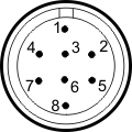
8-pin Hirose connector (HR25-7TR-8PA(73))
Pin |
Description |
 Fig. 376: USB 3 uEye CP Rev. 2, Hirose connector male, camera rear view |
|---|---|---|
1 |
Ground (GND) |
|
2 |
Flash output with optocoupler (-) |
|
3 |
General purpose I/O (GPIO) 1, 3.3 V |
|
4 |
Trigger input with optocoupler (-) |
|
5 |
Flash output with optocoupler (+) |
|
6 |
General purpose I/O (GPIO) 2, 3.3 V |
|
7 |
Trigger input with optocoupler (+) |
|
8 |
Output supply voltage, 5 V (100 mA) |
You can check the color assignment of the cable on the Website directly at the specific accessory item.
 |
The maximum length of the I/O cable is 30 m. The cable must be shielded. |
Power supply
The camera is supplied with power via the USB 3.0 interface. For information on the camera's power consumption, please refer to the Camera and sensor data section.
