IDS Software Suite 4.96.1
|
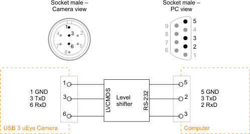
NOTICE! The General Purpose I/Os are not potential-free and have no protective circuit. Faulty wiring (overvoltage, undervoltage or inverting the wiring when used as serial interface) can result in a damage in the electronics. During operation as serial interface only LVCMOS levels are allowed to the connector pins. To get a serial RS-232 compliant interface, an external level shifter (LVCMOS/RS-232) is required. Applying RS-232 levels directly to the pins as well as mixing up the signals RxD and TxD can destroy the camera electronics! |
Serial interface specification
Minimum output voltage |
|
Min. |
Max. |
|
|---|---|---|---|---|
Signal level "Low" |
0 |
0.8 |
V |
|
Signal level "High" |
2.0 |
4.0 |
V |
|
Maximum input voltage |
|
Min. |
Max. |
|
Signal level "Low" |
0 |
0.8 |
V |
|
Signal level "High" |
2.0 |
4.0 |
V |
|
Supported Baud rates |
9.600 19.200 38.400 57.600 115.200 |
baud |
||
Transmission mode |
Full duplex, 8N1 |
|
||
Data bits |
8 |
|
||
Stop bits |
1 |
|
||
Parity |
None |
|
||
|
With the 8N1 mode, the maximum payload data rate achievable is 80% of the selected baud rate. |
Serial interface wiring (UART)
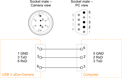
The following figure shows the wiring of the serial interface with GPIO 1 as camera-side output (TxD) and GPIO 2 as camera-side input (RxD). The GPIO must be configured accordingly (see is_IO()).

Fig. 383: Serial interface connector (UART)
Serial interface wiring (RS-232)

Fig. 384: Serial interface connector (RS-232)

