IDS Software Suite 4.96.1
Digitizing
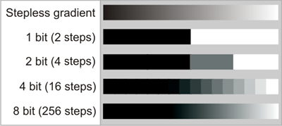
Image sensor pixels first generate an analog voltage signal proportional to the amount of light that strikes them. The image is digitized for further processing, i.e. the stepless signal is converted to a digital numerical value. The following figure shows this using a gray gradient as an example.

Fig. 44: Various bit depths using a gray-scale gradient as an example
If the stepless gradient is imaged in a digital range in 2 bits, for example, the result is 22 = 4 levels; for 4 bits, it is 24 = 16 levels, and so on. The intermediate brightness values of the original gradient are irreversibly lost after digitization.
With around 200 levels or more, the jumps in brightness can no longer be discerned with the eye, which is why current monitors and digital cameras use 8 bits (256 levels) per color channel (fully adequate for visualization).
If digital image data undergoes further image processing, a bit depth greater than 8 may be necessary. The computer is able to differentiate between these very fine differences in brightness (no longer discernable by the eye) and process them. This is why industrial cameras often use 12 bits.
Bit depth |
Brightness levels |
8 |
28 = 256 |
10 |
210 = 1024 |
12 |
212 = 4096 |
14 |
214 = 16.384 |
|
Greater bit depths require extremely low-noise image sensors, however. As soon as the differences in brightness created by noise are greater than the digitization levels, no further data is gained. |
Depending on the interface up to 12 bits/pixel are transferred, even if the sensor outputs a lower bit depth. The following table gives an overview of all combinations:
|
CMOS sensors |
CCD sensors |
|---|---|---|
USB 2.0 |
8 bit |
8 bit, 12 bit*4 |
USB 3.0 |
8 bit*1, 10 bit*1, 12 bit*1 |
- |
GigE |
8 bit*1, 10 bit*1, 12 bit*1 |
8 bit, 10 bit*2, 12 bit*3 |
*1 Depending on CMOS sensor (see Camera and sensor data)
*2 Camera date of manufacture till end of 2009
*3 Camera date of manufacture since 2010
*4 USB uEye cameras with hardware revision 3
|
Note on bit depth Color formats with a bit depth of more than 8 bits per channel are only supported by the following models: •GigE uEye series •uEye USB 3.1 series •USB 3 uEye series •USB 2.0 models with rev. 3 Using color formats with higher bit depth increases the bandwidth used by a camera. |
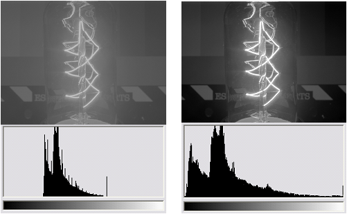
The brightness distribution of digital images is represented in a histogram. If an image has optimum contrast, the histogram includes practically all brightness values between 0 and the highest value (255 in 8-bit images). If an image has low contrast, the histogram only includes a small number of the values; the image appears dull:

Fig. 45: HDR image capture and histogram with minimal contrast (le.) and with optimum contrast after a contrast adjustment (ri.)
For improved display on the screen or when printed, the histogram can be spread to optimally utilize the possible brightness levels. For this purpose, the dark parts of the image are further darkened via an LUT characteristic and the light parts of the image are brightened. Thus the human eye can better differentiate between the different brightness levels; the image has more contrast.
It must be noted, however, that subsequent processing with a computer will not yield more data. Therefore, subsequent contrast adjustment via software is not necessary for use in image processing. The computer can differentiate between the differences in brightness without contrast adjustment.
Advantage of greater bit depth with contrast adjustment
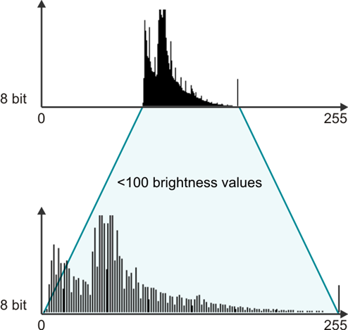
The bit depth in the output image is crucial for contrast adjustment. The following figures illustrate this. In the first example the 8-bit output image contains fewer than 100 brightness levels, as there are no dark or very bright parts. The image is low-contrast.
With a contrast adjustment, the values of the histogram are spread in such a way as to create a contrast-rich image. The fewer than 100 brightness values are now distributed across levels 0 to 255; gaps arise in the histogram and are visible as jumps in brightness in the resulting image.

Fig. 46: Contrast adjustment with 8-bit output data
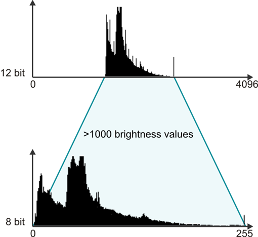
The second example shows the same output image with a 12-bit bit depth right at the time of capture. This image also has low contrast, as it features only average brightness values. The greater bit depth allows the brightness values of the image to be imaged over 1,000 different digital levels, however. The entire histogram includes 4,096 values in the 12-bit image (in contrast to 256 values with 8 bits).
This means that a contrast adjustment can now be made for screen display without a reduction in quality. The 1,000 values of the output image are distributed over the 256 values of the 8-bit target image in such a way that optimum contrast is the result. The large number of output values means that there are no gaps in the histogram.

Fig. 47: Contrast adjustment with 12-bit output data
|
This type of contrast adjustment can already be done in the camera when an image is digitized in 12 bits and transferred in 8 bit. In this case, optimum utilization of the 8 bit data is also important for image processing. |
