Why might I want a telecentric lens?
Metrology, when done optically, requires that an object’s representation be invariant to the distance and position in the field of view. Telecentric lenses deliver precisely that capability. Telecentric lenses only “pass” incoming light rays that are parallel to the optical axis of the lens. That’s helpful because we measure the distance between those parallel rays to measure objects without touching them.
Parallax effect
Human vision and conventional lenses have angular fields of view. That can be very useful, especially for depth perception. Our ability to safely drive a car in traffic derives in no small part from not just identifying the presence of other vehicles and hazards, but also from gauging their relative nearness to our position. In that context parallax delivers perspective, and is an asset!
But with angular fields of view we can only guess at the size of objects. Sure, if we see a car and a railroad engine side by side, we might guess that the car is about 5 feet high and the railroad engine perhaps 15 or 16 feet. In metrology we want more precision than to the nearest foot! In detailed metrology such as precision manufacturing we want to differentiate to sub-millimeter accuracy. Telecentric lenses to the rescue!
Telecentric Tutorial
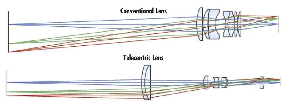
Telecentric lenses only pass incoming light rays that are parallel to the optical axis of the lens. It’s not that the oblique rays don’t reach the outer edge of the telecentric lens. Rather, it’s about the optical design of the lens in terms of what it passes on through the other lens elements and onto the sensor focal plane.
Let’s get to an example. In the image immediately below, labeled “Setup”, we see a pair of cubes positioned with one forward of the other. This image was made with a conventional (entocentric) lens, whereby all three dimensions appear much the same as for human vision. It looks natural to us because that’s what we’re used to. And if we just wanted to count how many orange cubes are present, the lens used to make the setup image is probably good enough.
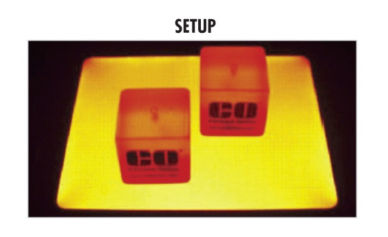
But suppose we want to measure the X and Y dimensions of the cubes, to see if they are within rigorous tolerance limits?
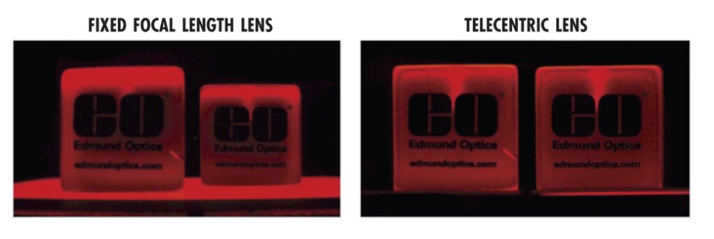
An object-space telecentric lens focuses the light without the perspective of distance. Below, the image on the left is the “straight on” view of the same cubes positioned as in “Setup” above, taken with a conventional lens. The forward cube appears larger, when in fact we know it to be exactly the same size.
The rightmost image below was made with a telecentric lens, which effectively collapses the Z dimension, while preserving X and Y. If measuring X and Y is your goal, without regard to Z, a telecentric lens may be what you need.
How to select a telecentric lens?
As with any engineering challenge, start by gathering your requirements. Let’s use an example to make it real.
Object size
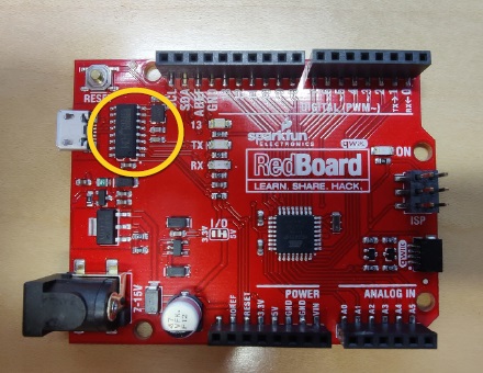
What is your object size? What is the size of the surrounding area in which successive instances of the target object will appear? This will determine the Field of View (FOV). In the example above, the chip is 6mm long and 4mm wide, and the boards always present within 4mm. So we’ll assert 12mm FOV to add a little margin.
Pixels per feature
In theory, one might get away with just two pixels per feature. In practice it’s best to allow 4 pixels per feature. This helps to identify separate features by permitting space between features to appear in contrast.
Minimum feature size
The smallest feature we need to identify is the remaining critical variable to set up the geometry of the optical parameters and imaging array. For the current example, we want to detect features as small as 25µm. That 25µm feature might appear anywhere in our 12mm FOV.
Example production image
Before getting into the calculations, let’s take a look at an ideal production image we created after doing the math, and pairing a camera sensor with a suitable telecentric lens.
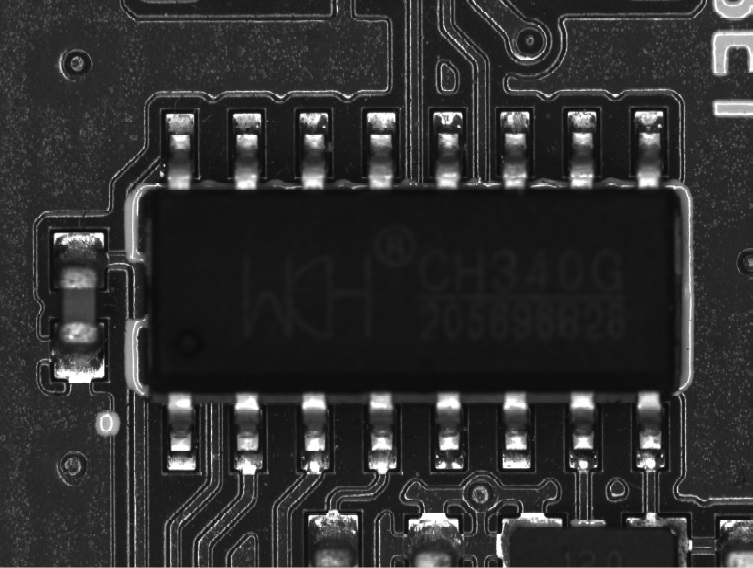
The logic chip image above was obtained with an Edmund Optics SilverTL telecentric lens – in this case the 0.5X model. More on how we got to that lens choice below. The key point for now is “wow – what a sharp image!”. One can not only count the contacts, but knowing our geometry and optical design, we can also inspect them for length, width, and feature presence/absence using the contrast between the silver metallic components against the black-appearing board.
Resuming “how to choose a telecentric lens?”
So you’ve got an application in mind for which telecentric lens metrology looks promising. How to take the requirements figures we determine above, and map those to camera sensor selection and a corresponding telecentric lens?
Method 1: Ask us to figure it out for you.
It’s what we do. As North America’s largest stocking distributor, we represent multiple camera and lens manufacturers – and we know all the products. But we work for you, the customer, to get the best fit to your specific application requirements.

Method 2: Take out your own appendix
Let’s define a few more terms, do a little math, and describe a “fitting” process. Please take a moment to review the terms defined in the following graphic, as we’ll refer to those terms and a couple of the formulas shortly.
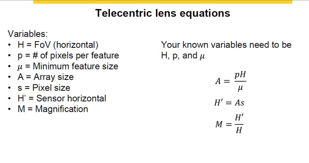
For the chip inspection application we’re discussing, we’ve established the three required variables:
H = FOV = 12mm
p = # pixels per feature = 4
µ = minimum feature size = 25µm
Let’s crank up the formulas indicated and get to the finish line!
Determine required array size = image sensor
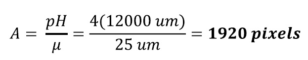
So we need about 1900 pixels horizontally, plus or minus – with lens selection, unless one designs a custom lens, choosing an off-the-shelf lens that’s close enough is usually a reasonable thing to do.
Reviewing a catalog of candidate area scan cameras with horizontal pixel counts around 1900, we find Allied Vision Technology’s (AVT) Manta G-131B, where G indicates a GigEVision interface and B means black-and-white as in monochrome (vs. the C model that would be color). This camera uses a sensor with 2064 pixels in the horizontal dimension, so that’s a pretty close fit to our 1920 calculation.
Determine horizontal size of the sensor
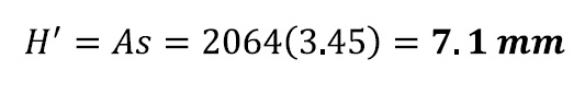
Per Manta G-319 specs, each pixel is 3.45µm wide, so 20643.(45) = 7.1mm sensor width.
Determine magnification requirements
The last formula tells us the magnification factor to fit the values for the other variables:
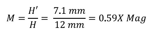
Choose a best-fit telecentric lens
Back to the catalog. Consider the Edmund Optics SilverTL Series. These C-mount lenses work with sensor sizes 1/2″, 2/3″, and 1/1.8″ sensors, and pixels as small as 2.8µm, so that’s a promising fit for the 1/1.8″ sensor at 3.45µm pixel size found in the Manta G-131B. Scrolling down the SilverTL Series specs, we land on the 0.50X Silver TL entry:
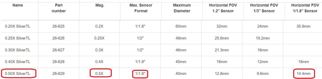
The 0.5x magnification is not a perfect fit to the 0.59x calculated value. Likewise the 14.4mm FOV is slightly larger than the 12mm calculated FOV. But for high-performance ready-made lenses, this is a very close fit – and should perform well for this application.
Optics fitting is part science and part experience – and of course one can “send in samples” or “test drive” a lens to validate the fit. Take advantage of our experience in helping customers match application requirements to lens and camera selection, as well as lighting, cabling, software, and other components.

1st Vision’s sales engineers have over 100 years of combined experience to assist in your camera and components selection. With a large portfolio of cameras, lenses, cables, NIC cards and industrial computers, we can provide a full vision solution!
About you: We want to hear from you! We’ve built our brand on our know-how and like to educate the marketplace on imaging technology topics… What would you like to hear about?… Drop a line to info@1stvision.com with what topics you’d like to know more about