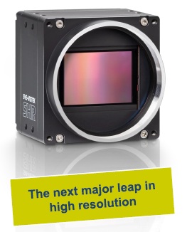
245 MP cameras in both monochrome and color models
SVS-Vistek, with 35 years experience developing machine vision cameras, releases their first SHR811 Super High Resolution cameras. Additional sensors and cameras will be released in the coming months. The first two SHR models, one each in monochrome and color, are based on the Sony IMX811 CMOS sensor.
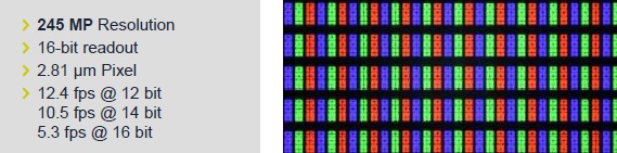
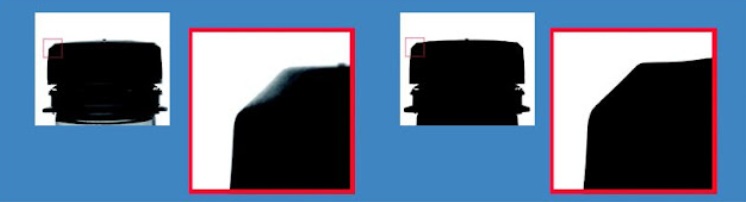
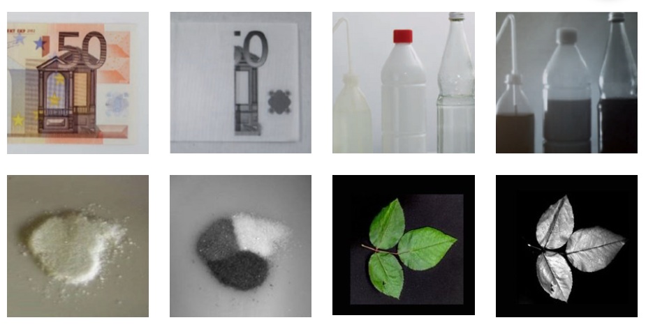
The right-hand image above may look like just a color grid – in fact it’s a segment of a 245 MP image from an LCD inspection application. So imagine a large HDTV or other flat panel showing a test pattern as part of post-production quality acceptance testing. The image is a segment of the inspection image showing just a subset grid of the activated pixels – at such resolution that machine vision algorithms can conclusively give each panel a clear pass or fail determination.
Frame rates to 12 fps might not sound impressive for certain applications, but for a 245 MP sensor, it’s pretty compelling. That’s achieved with the CoaXPress (CSP) interface.

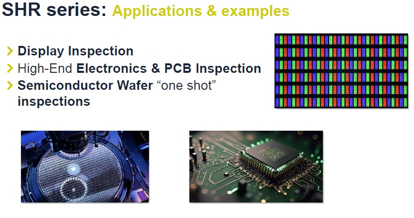
Applications and Examples
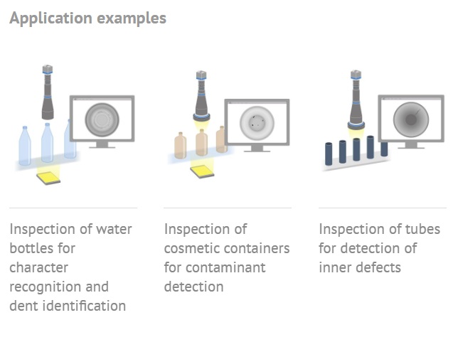
The series name – SHR – already suggests the applications for which these cameras are intended – Super High Resolution. You may have innovative applications of your own, but classical uses include:
- Electronics and PCB inspection
- Display inspection
- Semiconductor wafer inspection
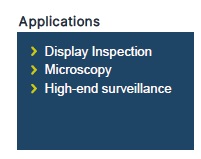
- Microscopy
- High-end surveillance
Additional applications include microscopy and surveillance:
Courtesy SVS-Vistek
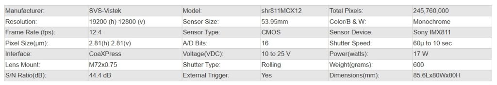
Technical details
Based on the Sony IMX411, this remarkable sensor is the key technology around which SVS-Vistek has designed the SHR811 launch-model camera.
This sensor has 62% higher pixel density than the highly-successful Sony IMX411 sensor, at 2x the framerate, and similar sensor size. So it’s a classic example of Moore’s Law, with size reduction and performance improvements, as Sony builds on its track record of innovation.
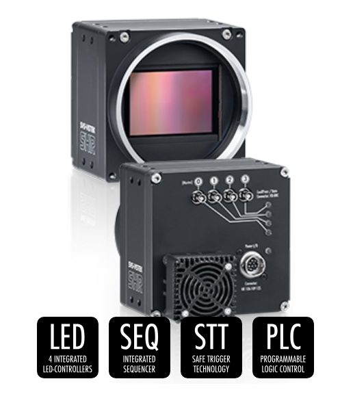
Features
As one would expect, there is a comprehensive feature set, including:
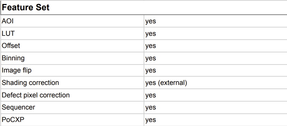
To highlight one specific feature, consider the Sequencer capability. It allows a single trigger to begin a series of timed exposures, as described in the following short video:
For full specifications, go to the SVS-Vistek SHR camera family, drill in to a specific model, and see or download PDF Datasheet, Manual, Technical Drawing, and/or Sensor Spec. Or just call us at 978-474-0044 and let us guide you.

1st Vision’s sales engineers have over 100 years of combined experience to assist in your camera and components selection. With a large portfolio of cameras, lenses, cables, NIC cards and industrial computers, we can provide a full vision solution!
About you: We want to hear from you! We’ve built our brand on our know-how and like to educate the marketplace on imaging technology topics… What would you like to hear about?… Drop a line to info@1stvision.com with what topics you’d like to know more about.