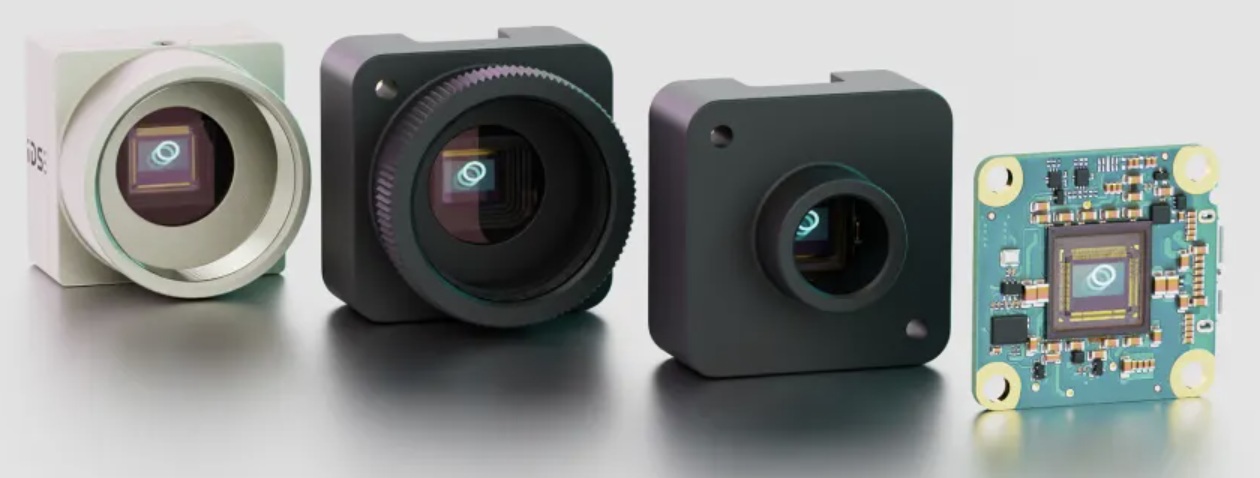
Recently we introduced the IDS Imaging event-based cameras, the uEye XCP-E models. These cameras are a paradigm shift – they detect changes in pixel brightness and transmit ONLY those changes. This dramatically reduces data load, lowers latency, and improves efficiency.

Speed, speed, speed
Temporal resolution is better than 100μsec! Rapid changes can be detected – equivalent to an area scan camera operating at >10,000fps.
Paradigm shift – from “frames” to “events”
This is one of those aha moments. Too often we get jaded in believing that things only evolve incrementally – Moore’s law and electronics getting faster and less expensive, etc. Yawn. But this really is a game changer worth getting one’s head wrapped around.
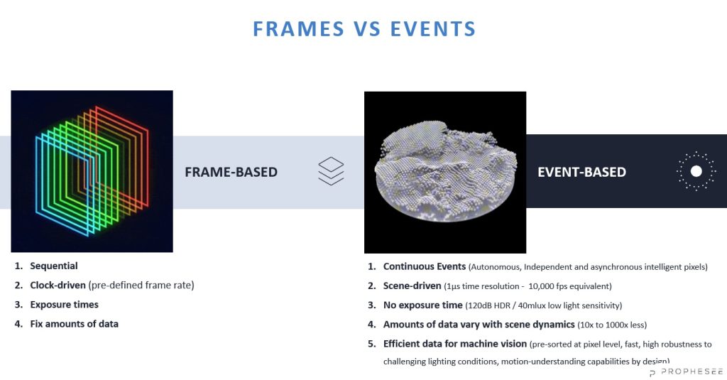
The event-based vision sensor (EVS) was developed by Sony and Prophesee.

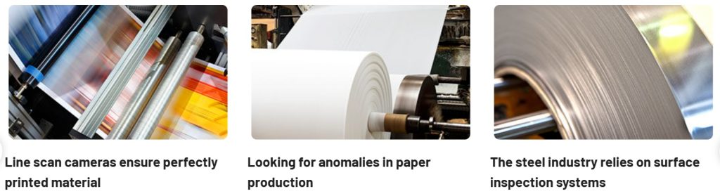
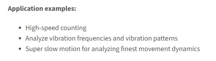
Industrial use cases
With a radically new technology, even machine vision veterans may appreciate seeing example applications already utilizing event-based imaging:
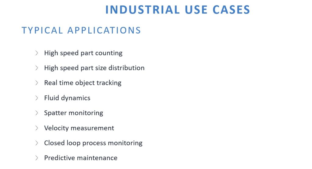
Example applications
The following are meant to be suggestive rather than inclusive. Just to whet the appetite.
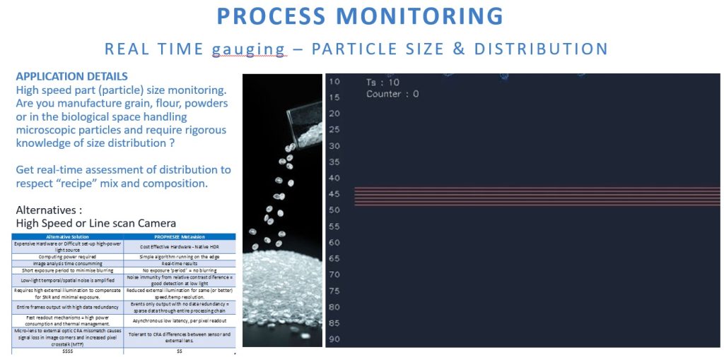
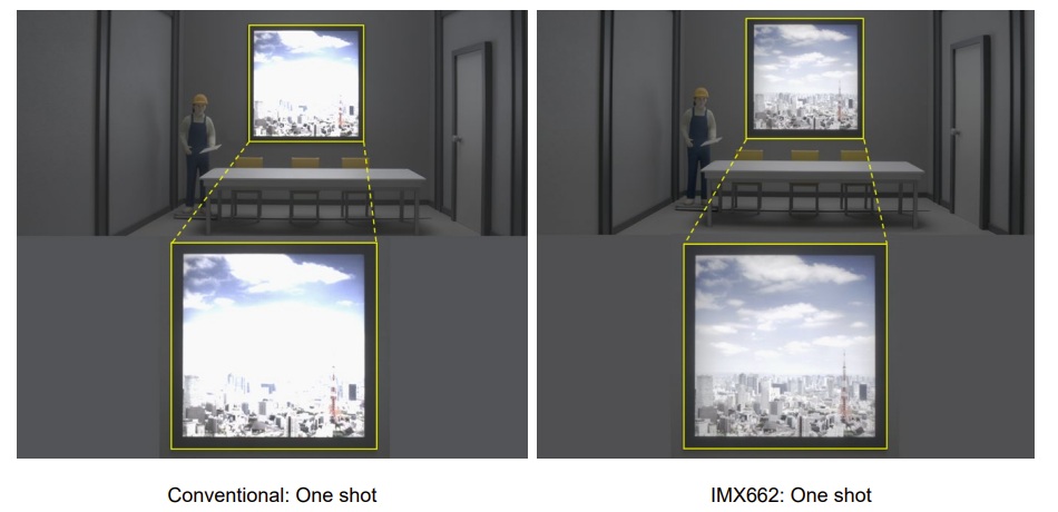
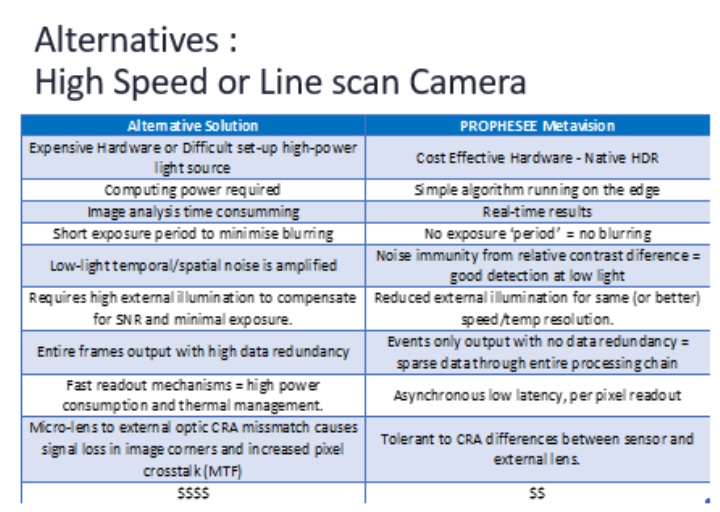
Let’s enlarge that “alternatives” comparison from the above graphic:
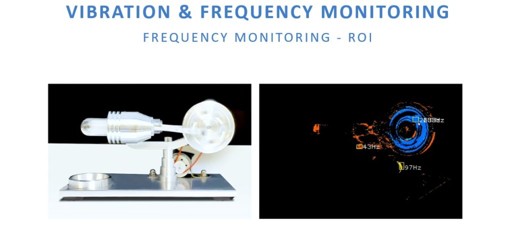
Another class of applications
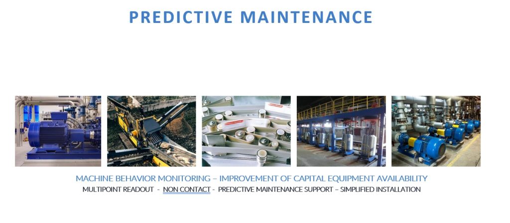
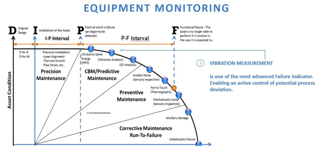
Take the guesswork out of when to do preventative maintenance. Maximize uptime. Reduce the risks of catastrophic failure. These cameras are affordable enough to let them do the vibration monitoring – just set your alert threshold!
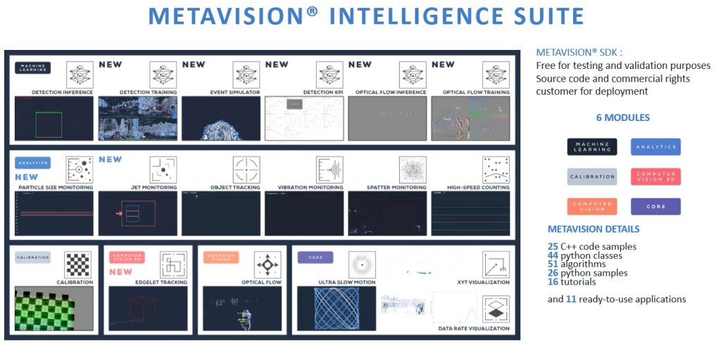
Software for event-based imaging applications

Get it? Got it? Need it? Want it?
This is a new way of coming at machine vision applications. It may give you an edge over your competition by enabling you to improve quality, reduce costs, and/or innovate new products or services. It really is different. See the IDS Imaging uEye XCP-E event-based cameras and datasheets. Powered by the Sony IMX636 developed in conjunction with Prophesee.
Tell us more about your application, using the link below. Or just call us at 978-571-5552. We can help you determine whether event-based imaging is optimal for your application.

1st Vision’s sales engineers have over 100 years of combined experience to assist in your camera and components selection. With a large portfolio of cameras, lenses, cables, NIC cards and industrial computers, we can provide a full vision solution!
About you: We want to hear from you! We’ve built our brand on our know-how and like to educate the marketplace on imaging technology topics… What would you like to hear about?… Drop a line to info@1stvision.com with what topics you’d like to know more about.