Z-Trak Express 5k profiles per second

For 3D in-line measurement and inspection applications across various industries such as battery, automotive, lumber inspection, factory automation, logistics, and more. Constant profile rate of 5,000 profiles per second, along with real-time processing. Cost-effective, eye-safe red or blue lasers. Up to 1,700 mm field-of-view. Up to 675 mm Z-range.

Z-Trak Express laser line profiler series
– Courtesy Teledyne DALSA

Newest series in large Z-Trak product line

Teledyne DALSA now offers four distinct 3D laser profiler series in its Z-Trak product line. Each member of the four series is a compact high-performance 3D laser profiler sensor. Each delivers high resolution height measurements using laser triangulation techniques. Each 3D profiler is factory calibrated to ensure accurate, consistent results.

IP67 protection for harsh environments

And each is built with IP67 protection to withstand the demands of harsh industrial environments making them suitable for industrial applications such as factory automation, metrology, surface, semiconductor, and parts inspection.

contact us

Z-Trak Express in particular

Key features – Courtesy Teledyne DALSA
Additional features and capabilities – Courtesy Teledyne DALSA

Detailed specs for each member of the series

You can find all the specs in the datasheets. For all Z-Trak laser profilers, see the Z-Trak product family overview. Then drill in on any specific family for more information.

If you know it’s new Express products you want, see Z-Trak Express 3D laser profiler.

Sometimes a single Z-Trak profiler is enough

But for some applications one might want to combine two or more sensors, in various spatial configurations:

Combine multiple units according to application requirements – Courtesy Teledyne DALSA

To simplify deployment and reduce costs, the Z-Trak Express 1K5 synchronizes multiple sensors via the data cables and supports content-based triggering for enhanced flexibility.

Which Z-Trak 3D camera is best for my application?

See our blog on key characteristics of 3D laser profiling, as a basis for choosing among Z-Trak 3D cameras. Or let us guide you through it by phone: 978-474-0044. Or use the form below. Together we can do this!

1st Vision’s sales engineers have over 100 years of combined experience to assist in your camera and components selection.  With a large portfolio of cameraslensescablesNIC cards and industrial computers, we can provide a full vision solution!

About you: We want to hear from you!  We’ve built our brand on our know-how and like to educate the marketplace on imaging technology topics…  What would you like to hear about?… Drop a line to info@1stvision.com with what topics you’d like to know more about.

#3D

#profiler

High-resolution 5GigE SWIR Goldeye Pro cameras

Available in 5.3 and 3.2 MP sensor options, the 5 GigE interface delivers framerates exceeding 100 fps. Based on the TEC-version of Sony’s IMX992/993 SenSWIR sensors, the cameras are sensitive from 400nm to 1,700nm, so they are classified as VSWIR. With a single sensor covering both the visible and SWIR range, new economies are possible for applications needing that spectral coverage.

Even if you don’t need VIS and just want SWIR…

These are compelling for SWIR applications for two key reasons:

  1. They achieve impressive framerates for large sensors (by SWIR standards), at 115 fps for the 5.3 MP, and 159 fps for the 3.2 MP model. With a very affordable 5 GigE interface.
  2. Outstanding image quality ideal for demanding applications.
Goldeye Pro – Courtesy Allied Vision – a TKH Vision brand

Our previous “coming soon” blog summarized key features, suggested applications, and a first look, so below we’ll go deeper now that the products are fully released.

Thermoelectric cooling (TEC) for image quality

The InGaAs (indium gallium arsenide) sensors used for SWIR imaging deliver the best images when temperature-stabilized. That’s provided by the thermoelectric cooling (TEC). That helps reduce dark noise and thermal current.

Must an InGaAs SWIR camera use TEC?

No, it’s not a requirement. Allied Vision is a leading producer of SWIR cameras, and while many include thermoelectric cooling, certain models do not. See all Allied Vision SWIR cameras and note some are “TECless.”

Whether your application requires TEC or not comes down to framerates, duty cycles, and overall performance demands. As with many engineering and design questions, how good is good enough?

Overview

Here are the key specifications at a glance:

Goldeye Pro models at a glance – Courtesy Allied Vision – a TKH Vision brand

For price quote or more information on either:

Goldeye Pro 5GigE G5-320 VSWIR TEC1Goldeye Pro 5GigE G5-530 VSWIR TEC1
Contact us

Features of note

Both models offer 12- and 10-bit sensor readout modes for achieving the highest possible dynamic range.

Both offer region-of-interest control to speed up frame rates and optimize bandwidth usage.

Both offer look-up tables to increase contrast.

Both provide digital binning and gain control to increase sensitivity.

And there are multiple user sets are available to simplify camera setup.

Applications

SWIR sees things that visible imaging cannot. (Likewise for UV, but that’s beyond the scope of this piece.) SWIR imaging can be mapped to “pseudo” images for human viewing – if required.

More to the point, machine vision applications get the job done in real-time without human involvement. Sort those materials. Monitor the perimeter for intruders. Optimize crop irrigation. etc.

If SWIR pseudo images help to get the juices flowing, here are a few:

Visible vs. SWIR image pairs – Courtesy Allied Vision – a TKH Vision brand
Contact us for a quote

Vision Systems Design award-winner

While the award was earned in China, the cameras perform the same in whatever country they are deployed in.

1st Vision’s sales engineers have over 100 years of combined experience to assist in your camera and components selection.  With a large portfolio of cameraslensescablesNIC cards and industrial computers, we can provide a full vision solution!

About you: We want to hear from you!  We’ve built our brand on our know-how and like to educate the marketplace on imaging technology topics…  What would you like to hear about?… Drop a line to info@1stvision.com with what topics you’d like to know more about.

Whitepaper: Event-based sensing paradigm

Except for sometimes compelling line-scan imaging, machine vision has been dominated by frame-based approaches. (Compare Area-scan vs. Line-scan). With an area-scan camera, the entire two-dimensional sensor array of x pixels by y pixels is read out and transmitted over the digital interface to the PC host. Whether USB3, GigE, CoaXPress, CameraLink, or any other interface, that’s a lot of image data to transport.

Download whitepaper
Event-based sensing as alternative to frame-based approach

If your application is about motion, why transmit the static pixels?

The question above is intentionally provocative, of course. One might ask, “do I have a choice?” With conventional sensors, one really doesn’t, as their pixels just convert light to electrons according to the physics of CMOS, and readout circuits move the array of charges on down the interface to the host PC, for algorithmic interpretation. There’s nothing wrong with that! Thousands of effective machine vision applications use precisely that frame-based paradigm. Or the line-scan approach, arguably a close cousin of the area-scan model.

Consider the four-frame sequence to the left, relative to a candidate golf-swing analysis application. Per the legend, with post-processing markup the blue-tinged golfer, club, and ball are undersampled in the sense that there are unshown phases of the swing.

Meanwhile the non-moving tree, grass, and sky are needlessly re-sampled in each frame.

It takes an expensive high-frame-rate sensor and interface to significantly increase the sample rate. Plus storage capacity for each frame. And/or processing capacity – for automated applications – to separate the motion segments from the static segments.

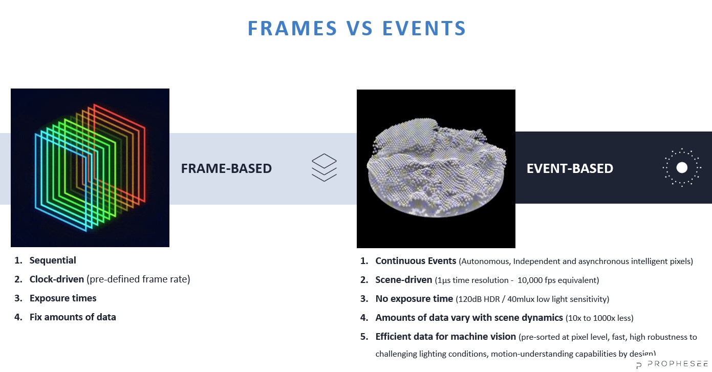
With event-based sensing, introduced below, one can achieve the equivalent of 10k fps – by just transmitting the pixels whose values change.

Images courtesy Prophesee Metavision.

Event-based sensing only transmits the pixels that changed

Unlike photography for social media or commercial advertising, where real-looking images are usually the goal, for machine vision it’s all about effective (automated) applications. In motion-oriented applications, we’re just trying to automatically control the robot arm, drive the car, monitor the secure perimeter, track the intruder(s), monitor the vibration, …

We’re NOT worried about color rendering, pretty images, or the static portions in the field of view (FOV). With event-based sensing, “high temporal imaging” is possible, since one need only pay attention to the pixels whose values change.

Consider the short video below. The left side shows a succession of frame-based images for a machine driven by an electric motor and belt. But the left hand image sequence is not a helpful basis for monitoring vibration with an eye to scheduling (or skipping) maintenance, or anticipating breakdowns.

The right-hand sequence was obtained with an event-based vision sensor (EVS), and absolutely reveals components with both “medium” and “significant” vibration. Here those thresholds have triggered color-mapped pseudo-images, to aid comprehension. But an automated application could map the coordinates to take action, such as gracefully shutting down the machine, scheduling maintenance according to calculated risk, etc.

Courtesy Prophesee Metavision

Another example to help make it real:

Here’s another short video, which brings to mind applications like autonomous vehicles and security. It’s not meant to be pretty – it’s meant to show the sensor detects and transmits just the pixels that correlate to change:

Courtesy Prophesee Metavision

Event-based sensing – it really is a different paradigm

Even (especially?) if you are seasoned at line-scan or area-scan imaging, it’s a paradigm shift to understand event-based sensing. Inspired by human vision, and built on the foundation of neuromorphic engineering, it’s a new technology – and it opens up new kinds of applications. Or alternative ways to address existing ones.

Download whitepaper
Event-based sensing as alternative to frame-based approach

Download the whitepaper and learn more about it! Or fill out our form below – we’ll follow up. Or just call us at 978-474-0044.

1st Vision’s sales engineers have over 100 years of combined experience to assist in your camera and components selection.  With a large portfolio of cameraslensescablesNIC cards and industrial computers, we can provide a full vision solution!

About you: We want to hear from you!  We’ve built our brand on our know-how and like to educate the marketplace on imaging technology topics…  What would you like to hear about?… Drop a line to info@1stvision.com with what topics you’d like to know more about.
#EVS

#event-based

#neuromorphic

Guidelines selecting machine vision camera interface

Machine Vision Interfaces

Industrial machine vision camera interfaces continue to develop, allowing cameras to transfer megapixel images at extremely high frame rates.  These advancements open up endless applications, however each machine vision camera interface has its own pros and cons.

Selecting the best digital camera interface can be done by taking in several considerations, helping you to make an optimal selection.

The following are some considerations in making an interface selection.

  1. Bandwidth (Resolution and frame rate)
  2. Cable Length
  3. Cost
  4. Complexity

Updated whitepaper available

For a comprehensive treatment of these issues, links to various standards and products, and a helpful comparative table, download our freshly updated whitepaper Camera Interfaces Explained:

Download whitepaper
Download whitepaper Camera Interfaces Explained

Some of what’s in that whitepaper – just a teaser view

Bandwidth:  This is one of the biggest factors in selecting an interface as it essentially is the size of the pipe to allow data to flow.  Bandwidth can be calculated by (resolution) x (frame rate) x (bit depth).   You essentially find out pixels / second x the frame bit depth resulting in your total Megabits / second (Mb/sec).  Large frame sizes at high speeds will require a large data pipe!  If not, you’ll be bandwidth limited, so one would need to reduce the frame rate and image size or a combination of both.

Cable Length:  The application will dictate the distance between the camera and industrial computer.  In factory automation applications, the cameras can be located in most cases within meters from the computer vs a stadium sports analytics application requiring 100’s of meters.

Assorted machine vision cables – Courtesy CEI

Cost:  Budgets must also be considered.  Interfaces such as USB are very low cost versus a CoaxPress interface which will require a $2K frame grabber and more expensive cables.

Complexity:  Not all interfaces are plug and play and require more complex configuration.  If you are leaning towards interfaces using frame grabbers and have no vision experience, you may want to elect using a certified systems integrator.

Digital machine vision camera interfaces

The interfaces each have pros and cons aside from the designated bandwidth, cable lengths and costs, and are outlined as follows:

USB2.0 is an older standard for machine vision cameras and now superseded by USB3.0 / 3.1 .  Early on, this was popular allowing cameras to easily plug and play with standard USB ports.  This is still a great option for lower frame rate applications and comes with low cost.  Click here for USB2 cameras.

USB3.0 / 3.1  is the next revision of USB2.0 allowing high data rates, plug and play capabilities and is ratified by the AIA standards, being “USB3 Vision” compliant.  This allows plug and play with 3rd party software following the GENICAM standards.  Cables lengths are limited to 5 meters, but can be overcome with active and optical cables.   Click here for USB3 cameras

GigE Vision was introduced in 2006 and is a widely accepted standard following GENICAM standards.  This is a the most popular high bandwidth interface allowing plug and play capabilities and allowing long cable lengths.  Power Over Ethernet (PoE) will allow 1 cable to be used for data and power making a simpler installation.  GigE is still not was fast as USB3.0, but has benefits of 100 meter cable lengths.  Click here for GigE cameras.

5 GiGe (aka N-base T) & 10GigE similar to USB2 moving to USB3, is the next iteration of the GigEVision standard providing more bandwidth.   Both follow the same GigE Vision standards, but now at higher bandwidths.  Specific NIC cards will be required to handle the interface.  Click here for 5 GigE cameras. 

The following interfaces typically require frame grabbers:

CoaxPress (CXP) is a relatively new standard released in 2010, supported by GENICAM, utilizing coax cable to transmit data, trigger signals and power using one cable..  It is a scaleable interface via additional coax cables supporting up to 25Gb/s (3125MB/s) and higher now with CXP12.  The interface can support extremely high bandwidth as seen in the above chart with long cable lengths to 100+ meters depending on the configuration.  This interface requires a frame grabber which adds cost and some complexity in the overall setup.  Click here for CoaxPress cameras

Camera link is a well established standard, dedicated machine vision standard released in 2000 allowing high speed communications between cameras and frame grabbers.  It includes provisions for data, communications, camera timing and real time signaling to the camera.  A frame grabber is required similar to CXP adding cost and some complexity and is limited in cable lengths to 10 meters.  Longer cable lengths can be achieved with active and fiber optic cable solutions which additionally add cost.   Click here for CameraLink cameras

CameraLink HS is a dedicated machine vision standard taking key aspects of CameraLink and expanding upon it with more features.  This is a scaleable high speed interface with reliable data transfer and long cable lengths up to 300+ meters with low cost fiber connections.  Similar to CXP and camera link a frame grabber is required adding cost.  Click here for Cameralink HS cameras


Only in the full whitepaper:

Single-table one-page comparison of key interface attributes, including data throughput, cable lengths, powering options.

DOWNLOAD WHITEPAPER TO VIEW COMPREHENSIVE TABLE

Helpful tips and practical advice

Emerging standards updates

For a comprehensive treatment of these issues download our freshly updated whitepaper Camera Interfaces Explained:

Download whitepaper
Download whitepaper Camera Interfaces Explained

If you prefer to be guided, just call us at 978-474-0044. Tell our sales engineer a bit about your application, and we’ll help guide you to a best-fit solution.

1st Vision’s sales engineers have over 100 years of combined experience to assist in your camera and components selection.  With a large portfolio of cameraslensescablesNIC cards and industrial computers, we can provide a full vision solution!

About you: We want to hear from you!  We’ve built our brand on our know-how and like to educate the marketplace on imaging technology topics…  What would you like to hear about?… Drop a line to info@1stvision.com with what topics you’d like to know more about.