Color models join Teledyne DALSA AxCIS Line Scan Series

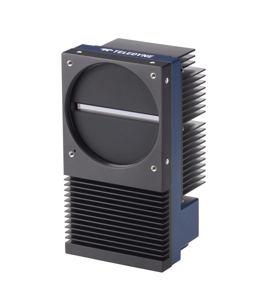
As anticipated when Teledyne DALDA’s AxCIS Line Scan Series was introduced a few months ago, color models have now been released. The “CIS” in the product name stands for Contact Image Sensor. In fact a CIS doesn’t actually contact the object being imaged – but it’s so close to touching that the term has become vision industry jargon to help us orient to the category.

Courtesy Teledyne DALSA

What can CIS do for me?

Think “specialized line scan”. Line scan in that it’s a linear array of sensors (vs. and area scan camera), requiring motion to create each successive next slice. And “specialized” in that CIS is positioned very close to the target, Plus low power requirements. And excellent price-performance characteristics.

Why is the new color offering interesting?

Just as with area scan imaging, if the application can be solved with monochrome sensors, that’s often preferred – since monochrome sensors, lensing, and lighting are simpler. If one just needs edge detection and contrast achievable with monochrome – stay monochrome! BUT sometimes color is the sole differentiator for an application, so the addition of color members to the AxCIS family can be a game changer.

Why Teledyne DALSA AxCIS in particular?

A longtime leader in line scan imaging, Teledyne DALSA introduces the AxCIS series in 2023 and continues to release new models and features. Vision Systems Design named the AxCIS family of high-speed high-resolution integrated imaging modules with their 2024 Gold Honoree Award.

Courtesy Vision Systems Design

AxCIS Series Key Attributes

  • Compact modules integrating sensors, lenses and lights
  • Option to customize the integrated lighting for specific CRI to aid in color measurement.
  • Current width choices 400mm (16 inches) or 800mm (32 inches)
  • Customizable lengths coming, in addition to the 400mm and 800mm models
  • CIS covers entire FOV – without missing any pixels and without using interpolation, allowing for accurate measurements. The competition has gaps between sensors causing areas which are not imaged and inability to measure properly
  • Selectable pixel sizes up to 900dpi
  • Gradient index lenses are used so there is no parallax and essentially telecentric.  (Great for gauging applications)  
  • Binning support, summed to provide brighter images
  • 4 available AOIs
  • CameraLink HS interface
  • Up to 120 kHz line rates … and cables lengths to 300m
  • No alignment or calibration required – lighting and sensors are pre-aligned
  • HDR imaging with dual exposure mode

Get quote

See specs for specific models in the Teledyne DALSA AxCIS Series.

Contact us for a quote

HDR – a closer look

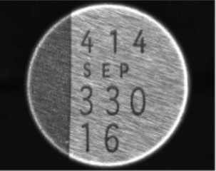
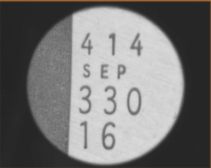
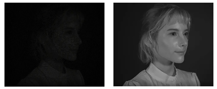
HDR Imaging – High Dynamic Range – Courtesy Teledyne DALSA

By using two adjacent rows of sensors, one row may be used for a short exposure to capture the rapidly saturated portions of an image. A second row of sensors can take a longer exposure, creating nuanced pixel values of areas that would otherwise have been undersaturated. Then the values are combined to a composite image with a wider dynamic range with more useful information to be interpreted by the processing algorithms.

Applications

While not limited to the following, popular applications include:

Popular AxCIS applications – Courtesy Teledyne DALSA

Want to see other Teledyne DALSA imaging products?

Teledyne DALSA is long-recognized as a leader and innovator across the diverse range of imaging products – click here to see all Teledyne DALSA products.

1st Vision’s sales engineers have over 100 years of combined experience to assist in your camera and components selection.  With a large portfolio of cameraslensescablesNIC cards and industrial computers, we can provide a full vision solution!

About you: We want to hear from you!  We’ve built our brand on our know-how and like to educate the marketplace on imaging technology topics…  What would you like to hear about?… Drop a line to info@1stvision.com with what topics you’d like to know more about. 

AT – Automation Technology XCS 3D Sensor Laser Profiler

Ideal for industrial applications requiring precision, reliability, high speed, and high resolution, AT – Automation Technology’s XCS 3D sensor laser profiler 3070 WARP achieves speeds up to 200 kHZ with the dual head model. Even the single head can achieve 140 kHz. The key innovations in the XCS series are in the laser-line projection technology.

XCS 3D sensor laser profiler – Courtesy AT – Automation Technology

Aren’t all 3D sensor laser profilers similar?

Many indeed share underlying similarities. Often they use triangulation to make their measurement. And the output is a 3D profile (or point cloud) of a target, built up by rapid laser pulsed stepwise “slices” of the X dimension as the target (or sensor) moves in the Y dimension. Triangulation determines variances in the Z dimension based on how the laser angle reflects from the target surface coordinate onto the sensor. For a brief refresher on the concepts, see our overview article and illustrations.

What’s special about AT – Automation Technology’s XCS Series?

Key attributes are shown in the video and called out in the following text.

30 second overview of XCS series

Homogeneous thickness laser line

Using special optics, the XCS series projects a laser line of homogeneous thickness across the target surface. AT – Automation Technology uses Field Curvature Correction (FCC) to create the uniform projection, overcoming the so-called line “bow” effect. This enables precise scanning of even small structures – regardless of whether such features are in the middle or edge of the laser line. What’s the benefit for the customer? It enables applications with high repeatability and accuracy – such as for ball grid arrays (BGAs), pin grid arrays (PGAs), and surface mount devices (SMDs).

Clean Beam Technology

The XCS Series utilizes AT – Automation Technology’s own Clean Beam function to insure a precisely focused laser beam, effectively suppressing side lobe noise interference.. Clean Beam also assures a uniform intensity distribution, which also contributes to the reliably consistent results.

Scanning a pin-grid array (PGA) – Courtesy AT – Automation Technology

Optional Dual Head to avoid occlusion

X FOV 53mm +/-

X Resolution 13mm +/-

Z Range to 20mm

Z Resolution to 0.4 µm

GigE Vision interface, GenICam compliant

For plug and play configuration with networking cables and adapter cards familiar to many, the GigE Vision interface is one of the most popular machine vision standards. And GenICam compliance means you can use AT – Automation Technology’s software or diverse 3rd party SDKs.

Additional features

Automatic RegionTracking, Automatic RegionSearch, Multiple Regions, MultiPart, AutoStart, History Buffer, Multi-Slope, MultiPeak

contact us

Is the XCS 3D sensor laser profiler best for your application?

AT – Automation Technology is confident there are demanding users for whom the XCS 3D laser profiler delivers just the right value proposition. Is that what your application requires? But AT also provides 3 other product families of laser profilers, including the CS Series, the MCS Series, and the ECS Series. It all comes down to speed and resolution requirements, field of view (FOV), and cost.

1st Vision’s sales engineers have over 100 years of combined experience to assist in your camera and components selection.  With a large portfolio of cameraslensescablesNIC cards and industrial computers, we can provide a full vision solution!

About you: We want to hear from you!  We’ve built our brand on our know-how and like to educate the marketplace on imaging technology topics…  What would you like to hear about?… Drop a line to info@1stvision.com with what topics you’d like to know more about. 

Machine vision software –> Sapera Processing

Why read this article?

Generic reason: Compact overview of machine vision software categories and functionality.

Cost-driven reason: Discover that powerful software comes bundled at no cost to users of Teledyne DALSA cameras and frame grabbers. Not just the a viewer and SDK – though of course those – but select image processing software too.

contact us

Software – build or buy?

Without software machine vision is nowhere. The whole point of machine vision is to acquire an image and then process it with an algorithm that achieves something of value.

Whether it’s presence/absence detection, medical diagnostics, thermal imaging, autonomous navigation, pick-and-place, automated milling, or myriad other applications, the algorithm is expressed in software.

You might choose a powerful software library needing “just” parameterization by the user – or AI – or a software development kit (SDK) permitting nearly endless scope of programming innovation. Either way it’s the software that does the processing and delivers the results.

In this article, we survey build vs. buy arguments for several types of machine vision software. We make a case for Teledyne DALSA’s Sapera Software Suite – but it’s a useful read for anyone navigating machine vision software choices – wherever you choose to land.

Sapera Vision Software Suite – Courtesy Teledyne DALSA

Third-party or vision library from same vendor?

Third-party software

If you know and love some particular third-party software, such as LabView, HALCON, MATLAB, or OpenCV, you may have developed code libraries and in-house expertise on which it makes sense to double-down. Even if there are development or run time licensing costs. Do the math on total cost of ownership.

Same vendor for camera and software

Unless the third-party approach described above is your clear favorite, consider the benefits of one-stop shopping for your camera and your software. Benefits include:

  • License pricing: SDK and run-time license costs are structured to favor the customer who sourced his cameras and software from the same provider.
  • Single-source simplicity: Since the hardware and software come from the same manufacturer, it just works. They’ve done all the compatibility validation in-house. And the feature naming used to control the camera fully aligns with the function calls used in the software.
  • Technical support: When it all comes from one provider, if you have support questions there’s no finger pointing.

You – the customer/client – are the first party. It’s all about you. Let’s call the camera manufacturer the second party, since the camera and the sensor therein are at the heart of image acquisition. Should licensed software come from a third party, or from the camera manufacturer? It’s a good question.

contact us

Types/functions of machine vision software

While there are all-in-one and many-in-one packages, some software is modularized to fulfill certain functions, and may come free, bundled, discounted, open-source, or priced, according to market conditions and a developer’s business model. Before we get into commercial considerations, let’s briefly survey the functional side, including each of the following categories in turn:

  • Viewer / camera control
  • Acquisition control
  • Software development kit (SDK)
  • Machine vision library
  • AI training/learning as an alternative to programming

Point of view: Teledyne DALSA’s Sapera software packages by capability

Viewer / camera control – included in Sapera LT

When bringing a new camera online, after attaching the lens and cable, one initially needs to configure and view. Regardless of whether using GigE Vision, CameraLink, CameraLink HS, USB3 Vision, CoaXpress, or other standards, one must typically assign the camera a network address and set some camera parameters to establish communication.

A graphical user interface (GUI) viewer / camera-control-tool makes it easy to quickly get the camera up and running. The viewer capability permits an image stream so one can get the camera aligned, adjust aperture, focus, and imaging modes.

Every camera manufacturer and software provider offers such a tool. Teledyne DALSA calls theirs CamExpert, and it’s part of Sapera LT. It’s free for users of Teledyne DALSA 2D/3D cameras and frame grabbers.

CamExpert – Courtesy Teledyne DALSA

Acquisition control – included in Sapera LT

The next step up the chain is referred to as acquisition control. On the camera side this is about controlling the imaging modes and parameters to get the best possible image before passing it to the host PC. So, one might select a color mode, whether to use HDR or not, gain controls, framerate or trigger settings, and so on.

On the communications side, one optimizes depending whether a single camera is on the databus, or if bandwidth is being shared. Any vendor offering acquisition control software has provide all these controls.

Controlling image acquisition with GUI tools – Courtesy Teledyne DALSA

Those with Sapera LT can utilize Teledyne DALSA’s patented TurboDrive, realizing speed gains of x1.5 to x3, under GigE Vision protocol. This driver brings added bandwidth without needing special programming.

Software development kit (SDK) – included in Sapera LT

GUI viewers are great, but often one needs at least a degree of programming to fully integrate and control the acquisition process. Typically one uses a software development kit (SDK) for C++, C#, .NET, and/or Standard C. And one doesn’t have to start from scratch – SDKs almost always include programming examples and projects one may adapt and extend, to avoid re-inventing the wheel.

Teaser subset of code samples provided – Courtesy Teledyne DALSA

Sapera Vision Software allows royalty free run-time licenses for select image processing functions when combined with Teledyne DALSA hardware. If you’ve just got a few cameras, that may not be important to you. But if you are developing systems for sale to your own customers, this can bring substantial economies of scale.

Machine vision library

So you’ve got the image hitting the host PC just fine – now what? One needs to programmatically interpret the image. Unless you’ve thought up a totally new approach to image processing, there’s an excellent chance your application will need one or more of edge detection, bar code reading, blob analysis, flipping, rotation, cross-correlation, frame-averaging, calibration, or other standard methods.

A machine vision library is a toolbox containing many of these functions pre-programmed and parameterized for your use. It allows you to marry your application-specific insights with proven machine vision processes, so that you can build out the value-add by standing on the shoulders of machine vision developers who provide you with a comprehensive toolbox.

No surprise – Teledyne DALSA has an offering in this space too. It’s called Sapera Processing. It includes all we’ve discussed above in terms of configuration and acquisition control – and it adds a suite of image processing tools. The suite’s tools are best understood across three categories:

  • Calibration – advanced configuration including compensation for geometric distortion
  • Image processing primitives – convolution functions, geometry functions, measurement, transforms, contour following, and more
  • Blob analysis – uses contrast to segment objects in a scene; determine centroid, length and area; min, max, and standard deviation; thresholding, and more
Just some of the free included image processing primitives –
Courtesy Teledyne DALSA

So unless you skip ahead to the AI training/learning features of Astrocyte (next section), Sapera Processing is the programmer’s comprehensive toolbox to do it all. Viewer, camera configuration, acquisition control, and image evaluation and processing functions. From low-level controls if you want them, through parameterized machine vision functions refined, validated, and ready for your use.

AI training/learning as an alternative to programming

Prefer not to program if possible? Thanks to advances in AI, many machine vision applications may now be trained on good vs. bad images, such that the application learns. This enables production images to be correctly processed based on the training sets and the automated inference engine.

No coding required – Courtesy Teledyne DALSA

Teledyne DALSA’s Astrocyte package makes training simple and cost-effective. Naturally one can combine it with parameterized controls and/or SDK programming, if desired. See our recent overview of AI in machine vision – and Astrocyte.

1st Vision’s sales engineers have over 100 years of combined experience to assist in your camera and components selection.  With a large portfolio of cameraslensescablesNIC cards and industrial computers, we can provide a full vision solution!

About you: We want to hear from you!  We’ve built our brand on our know-how and like to educate the marketplace on imaging technology topics…  What would you like to hear about?… Drop a line to info@1stvision.com with what topics you’d like to know more about. 

Lens extension tube or close up ring increases magnification

Summary at a glance:

Need a close-up image your preferred sensor and lens can’t quite deliver? A glass-free extension tube or close up ring can change the optics to your advantage.

C-mount extension tube kit – Courtesy Edmund Optics

What’s an extension tube?

An extension tube is a metal tube one positions between the lens and the camera mount. It comes with the appropriate threads for both the lens and camera mount, so mechanically it’s an easy drop-in procedure.

By moving the lens away from the optical plane, the magnification is increased. Sounds like magic! Well almost. A little optical calculation is required – or use of formulas or tables prepared by others. It’s not the case than any tube of any length will surely yield success – one needs to understand the optics or bring in an expert who does.

S-mount extension tube kit – Courtesy Edmund Optics

Note: One can also just purchase a specific length extension tube. We’ve shown images of kits to make it clear there are lots of possibilities. And some may want to own a kit in order to experiment.

Example

Sometimes an off-the-shelf lens matched to the sensor and camera you prefer suits your optical needs as well as your available space requirements. By available space we mean clearance from moving parts, or ability to embed inside an attractively sized housing. Lucky you.

But you might need more magnification than one lens offers, yet not as much as the next lens in the series. Or you want to move the camera and lens assembly closer to the target. Or both. Read on to see how extension rings at varying step sizes can achieve this.

Navigating the specifications

Once clear on the concept, it’s often possible to read the datasheets and accompanying documentation, to determine what size extension tube will deliver what results. Consider, for example, Moritex machine vision lenses. Drilling in on an arbitrary lens family, look at Moritex ML-U-SR Series 1.1″ Format Lenses, then, randomly, the ML-U1217SR-18C.

ML-U1217SR-18C 12mm lens optimized for 3.45um pixels and 12MP sensors – Courtesy Moritex

If you’ve clicked onto the page last linked above, you should see a PDF icon labeled “Close up ring list“. It’s a rather large table showing which extension tube lengths may be used with which members of the ML-U-SR lens series, to achieve what optical changes in the Field-Of-View (FOV). Here’s a small segment cropped from that table:

Field-Of-View changes with extension tubes of differing lengths – Courtesy Moritex

Compelling figures from the chart above:

Consider the f12mm lens in the rightmost column, and we’ll call out some highlights.

Extension tube length (mm)WD (far)Magnification
01000.111x
258.20.164
513.50.414
5mm tube yields 86% closer WD and 4x magnification!

Drum roll here…

Let’s expand on that table caption above for emphasis. For this particular 12mm lens, by using a 5mm extension tube, we can move the camera 86% closer to the target than by using just the unaugmented lens. And we quadruple the magnification from 0.111x to 0.414x. If you are constrained to a tight space, whether for a one-off system, or while building systems you’ll resell at scale, those can be game-changing factors.

contact us

Any downside?

As is often the case with engineering and physics, there are tradeoffs one should be aware of. In particular:

  • The light reaching the focal plane is reduced, per the inverse square law – if you have sufficient light this may not have any negative consequences for you at all. But if pushed to the limit resolution can be impacted by diffraction.
  • Reduced depth of field – does the Z dimension have a lot of variance for your application? Is your application working with the center segment of the image or does it also look at the edge regions where field curvature and spherical aberrations may appear?

We do this

Our team are machine vision veterans, with backgrounds in optics, hardware, lighting, software, and systems integration. We take pride in helping our customers find the right solution – and they come back to us for project after project. You don’t have to get a graduate degree in optics – we’ve done that for you.

Give a brief idea of your application and we’ll provide options.

Related resources

You might also be interested in one or more of the following:

contact us

1st Vision’s sales engineers have over 100 years of combined experience to assist in your camera and components selection.  With a large portfolio of cameraslensescablesNIC cards and industrial computers, we can provide a full vision solution!

About you: We want to hear from you!  We’ve built our brand on our know-how and like to educate the marketplace on imaging technology topics…  What would you like to hear about?… Drop a line to info@1stvision.com with what topics you’d like to know more about.