If monochrome sensors and methods aren’t enough for your application, a machine vision color camera may be needed. And if color is needed, is “good enough” from a single sensor with a Bayer filter all you need? Or do you need the precision of a prism-based 3 sensor camera, one for each of R, G, and B? See our whitepaper Considerations for Color Machine Vision Cameras.
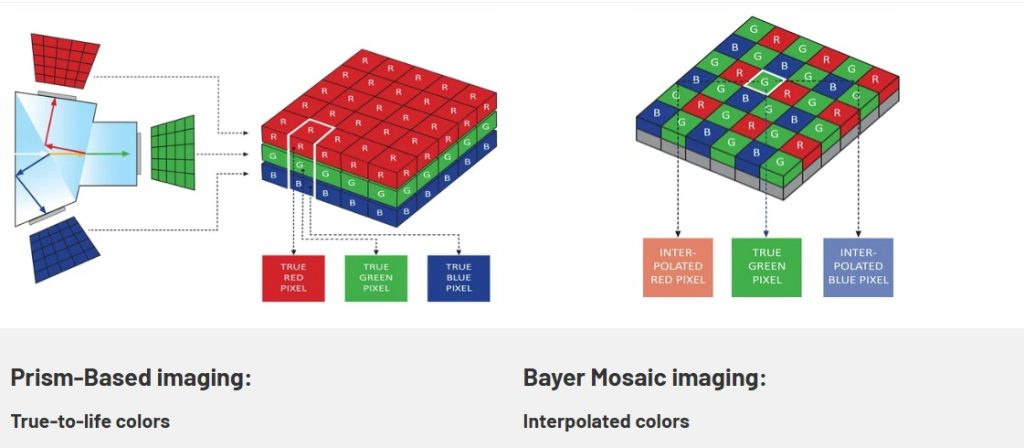
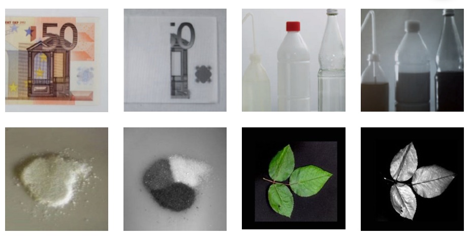
Bryce Bayer, the engineer at Eastman Kodak whose name is associated with his Bayer filter innovation, created a very compact and efficient way to layer a color filter atop a monochrome sensor. The vast majority of today’s color cameras – in both machine vision and consumer imaging – utilize precisely such a color filter mechanism to interpolate color. When the resolution is sufficiently fine, the rendered image is typically good enough for many applications.
But “good enough” for some isn’t the same as good enough for all
Interpolation is a form of estimation – in the case of a Bayer filter its design presumes that the Red, Green, and Blue values between each of the “true” measurements of those values is the average of the values at the accurate points. So the in-between values are computed, and may or may not correlate to the true color present at the source.
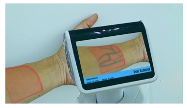
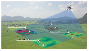
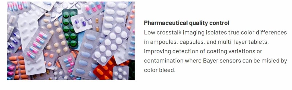
For certain machine vision, industrial imaging, and medical applications, maximum color accuracy is essential.
What’s best for my application?
Read on, for more detail. Or give us a call at 978-474-0044. Or tell us about your requirements and we’ll contact you.

For certain applications, color accuracy and fidelity is essential
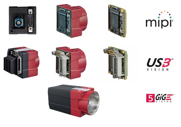
JAI adds 3 new 5.1 Mpix cameras to its Apex Series
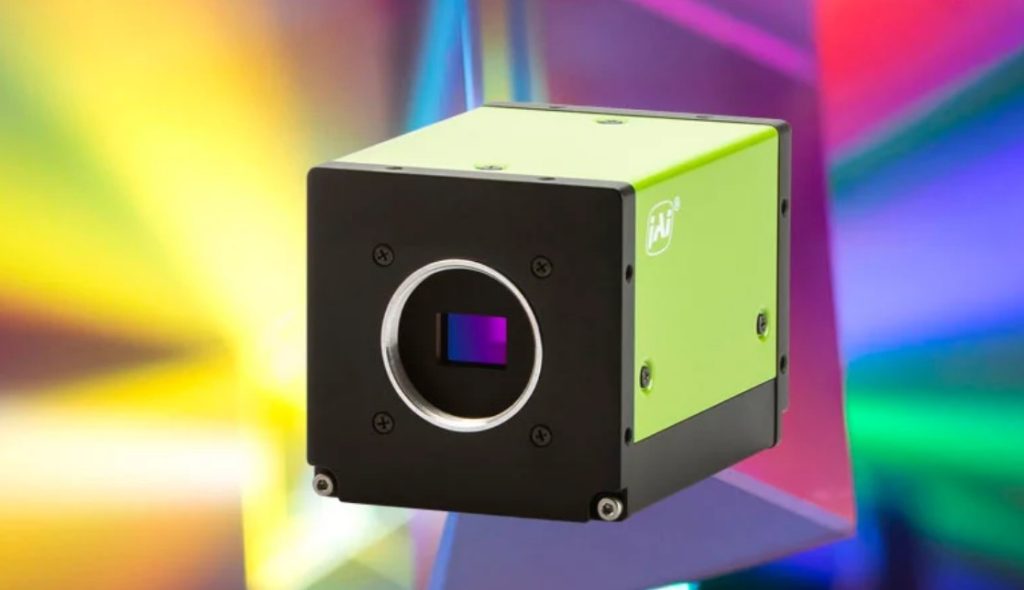
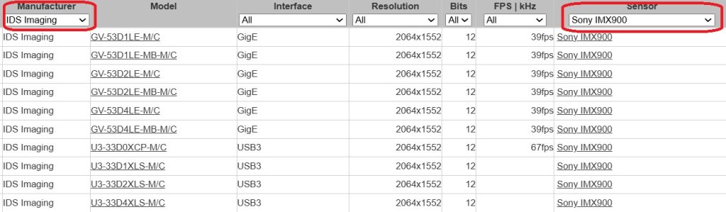
Previously JAI’s Apex prism-based camera series included 1.6 Mpix and 3.2 Mpix models. Three new models join the series, at 5.1 Megapixels each. The new members all use the same SONY IMX548, one of the Pregius S sensors.
If the new 5.1 Mpix models all use the same sensors, why are there three models? Because there are three interface options, depending on your need for speed.
- 5 GigE model: 32 fps
- CoaXpress model: 75 fps
- Camera Link model: 55 fps
Numerous features and benefits
There are many features designed into the Apex series cameras, including binning, single and multi-region ROI, chromatic aberration correction, and automatic level control. Download a manual for details. Or call us at 978-474-0044.
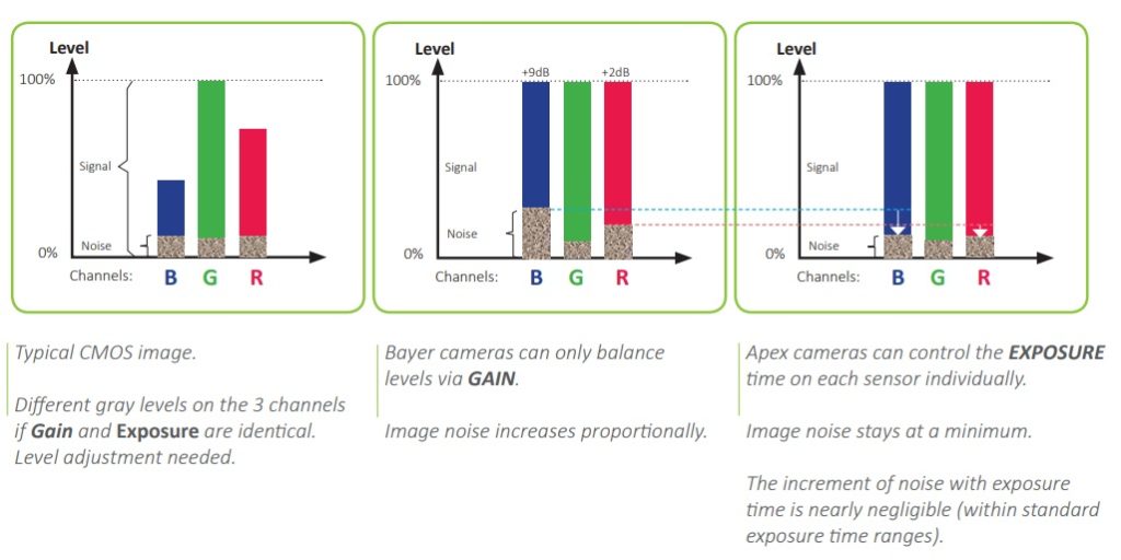
Feature highlight: Per-channel exposure control
Since the rationale for a 3 sensor prism camera is color performance, the per-channel exposure control feature helps to achieve that goal. By adjusting the exposure time for each channel separately, the camera increases signal without amplifying noise.
Call us at 978-474-0044 to learn more about JAI Apex cameras. Tell us about your application goals and requirements, and we’ll help you determine the best camera, lens, lighting, filters, and software. It’s what we do.

1st Vision’s sales engineers have over 100 years of combined experience to assist in your camera and components selection. With a large portfolio of cameras, lenses, cables, NIC cards and industrial computers, we can provide a full vision solution!
About you: We want to hear from you! We’ve built our brand on our know-how and like to educate the marketplace on imaging technology topics… What would you like to hear about?… Drop a line to info@1stvision.com with what topics you’d like to know more about.