Industrial machine vision camera interfaces continue to develop, allowing cameras to transfer megapixel images at extremely high frame rates. These advancements open up endless applications, however each machine vision camera interface has its own pros and cons.
Selecting the best digital camera interface can be done by taking in several considerations, helping you to make an optimal selection.
The following are some considerations in making an interface selection.
- Bandwidth (Resolution and frame rate)
- Cable Length
- Cost
- Complexity
Updated whitepaper available
For a comprehensive treatment of these issues, links to various standards and products, and a helpful comparative table, download our freshly updated whitepaper Camera Interfaces Explained:

Some of what’s in that whitepaper – just a teaser view
Bandwidth: This is one of the biggest factors in selecting an interface as it essentially is the size of the pipe to allow data to flow. Bandwidth can be calculated by (resolution) x (frame rate) x (bit depth). You essentially find out pixels / second x the frame bit depth resulting in your total Megabits / second (Mb/sec). Large frame sizes at high speeds will require a large data pipe! If not, you’ll be bandwidth limited, so one would need to reduce the frame rate and image size or a combination of both.
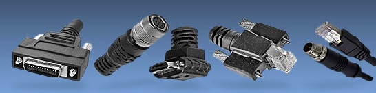
Cable Length: The application will dictate the distance between the camera and industrial computer. In factory automation applications, the cameras can be located in most cases within meters from the computer vs a stadium sports analytics application requiring 100’s of meters.
Cost: Budgets must also be considered. Interfaces such as USB are very low cost versus a CoaxPress interface which will require a $2K frame grabber and more expensive cables.
Complexity: Not all interfaces are plug and play and require more complex configuration. If you are leaning towards interfaces using frame grabbers and have no vision experience, you may want to elect using a certified systems integrator.
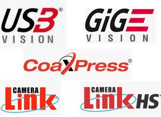
Digital machine vision camera interfaces
The interfaces each have pros and cons aside from the designated bandwidth, cable lengths and costs, and are outlined as follows:
USB2.0 is an older standard for machine vision cameras and now superseded by USB3.0 / 3.1 . Early on, this was popular allowing cameras to easily plug and play with standard USB ports. This is still a great option for lower frame rate applications and comes with low cost. Click here for USB2 cameras.
USB3.0 / 3.1 is the next revision of USB2.0 allowing high data rates, plug and play capabilities and is ratified by the AIA standards, being “USB3 Vision” compliant. This allows plug and play with 3rd party software following the GENICAM standards. Cables lengths are limited to 5 meters, but can be overcome with active and optical cables. Click here for USB3 cameras
GigE Vision was introduced in 2006 and is a widely accepted standard following GENICAM standards. This is a the most popular high bandwidth interface allowing plug and play capabilities and allowing long cable lengths. Power Over Ethernet (PoE) will allow 1 cable to be used for data and power making a simpler installation. GigE is still not was fast as USB3.0, but has benefits of 100 meter cable lengths. Click here for GigE cameras.
5 GiGe (aka N-base T) & 10GigE similar to USB2 moving to USB3, is the next iteration of the GigEVision standard providing more bandwidth. Both follow the same GigE Vision standards, but now at higher bandwidths. Specific NIC cards will be required to handle the interface. Click here for 5 GigE cameras.
The following interfaces typically require frame grabbers:
CoaxPress (CXP) is a relatively new standard released in 2010, supported by GENICAM, utilizing coax cable to transmit data, trigger signals and power using one cable.. It is a scaleable interface via additional coax cables supporting up to 25Gb/s (3125MB/s) and higher now with CXP12. The interface can support extremely high bandwidth as seen in the above chart with long cable lengths to 100+ meters depending on the configuration. This interface requires a frame grabber which adds cost and some complexity in the overall setup. Click here for CoaxPress cameras
Camera link is a well established standard, dedicated machine vision standard released in 2000 allowing high speed communications between cameras and frame grabbers. It includes provisions for data, communications, camera timing and real time signaling to the camera. A frame grabber is required similar to CXP adding cost and some complexity and is limited in cable lengths to 10 meters. Longer cable lengths can be achieved with active and fiber optic cable solutions which additionally add cost. Click here for CameraLink cameras
CameraLink HS is a dedicated machine vision standard taking key aspects of CameraLink and expanding upon it with more features. This is a scaleable high speed interface with reliable data transfer and long cable lengths up to 300+ meters with low cost fiber connections. Similar to CXP and camera link a frame grabber is required adding cost. Click here for Cameralink HS cameras
Only in the full whitepaper:
Single-table one-page comparison of key interface attributes, including data throughput, cable lengths, powering options.
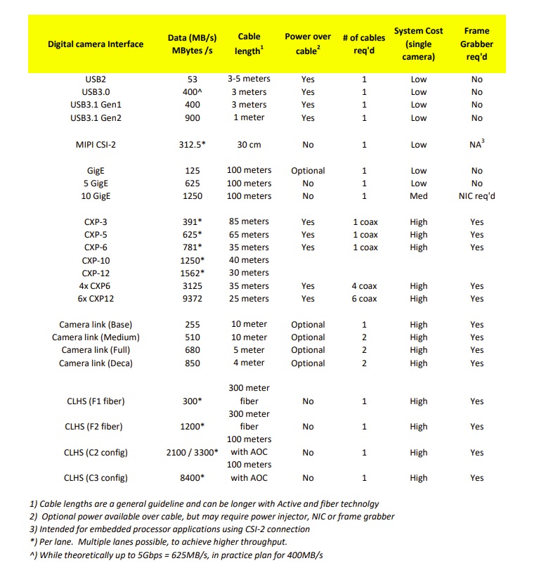
DOWNLOAD WHITEPAPER TO VIEW COMPREHENSIVE TABLE
Helpful tips and practical advice
Emerging standards updates
For a comprehensive treatment of these issues download our freshly updated whitepaper Camera Interfaces Explained:
If you prefer to be guided, just call us at 978-474-0044. Tell our sales engineer a bit about your application, and we’ll help guide you to a best-fit solution.

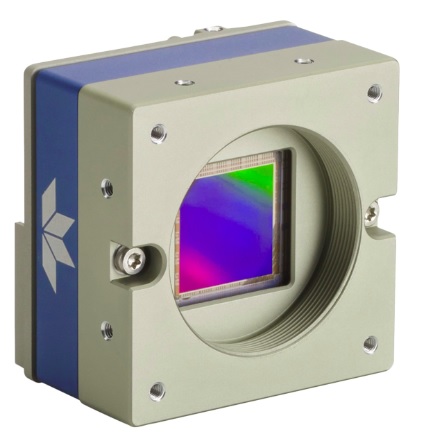
1st Vision’s sales engineers have over 100 years of combined experience to assist in your camera and components selection. With a large portfolio of cameras, lenses, cables, NIC cards and industrial computers, we can provide a full vision solution!
About you: We want to hear from you! We’ve built our brand on our know-how and like to educate the marketplace on imaging technology topics… What would you like to hear about?… Drop a line to info@1stvision.com with what topics you’d like to know more about.