JAI Wave WAA-1300-GE-TEC VIS SWIR camera

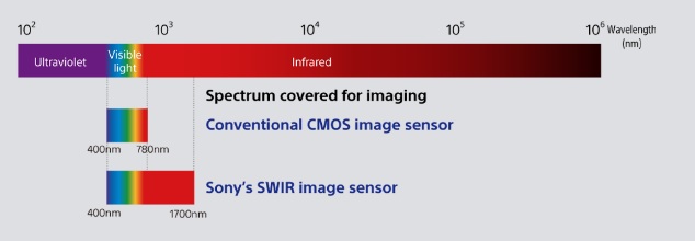
The Wave WAA-1300-GE-TEC combines visible and short-wave infrared (SWIR) sensitivity in a single camera, enabling enhanced material contrast, improved defect detection, and more reliable inspection results. With sensitivity from 400 nm to 1700 nm, the camera can reveal features and material characteristics that may not be visible using standard imaging technologies.

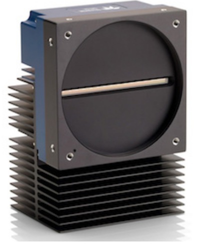
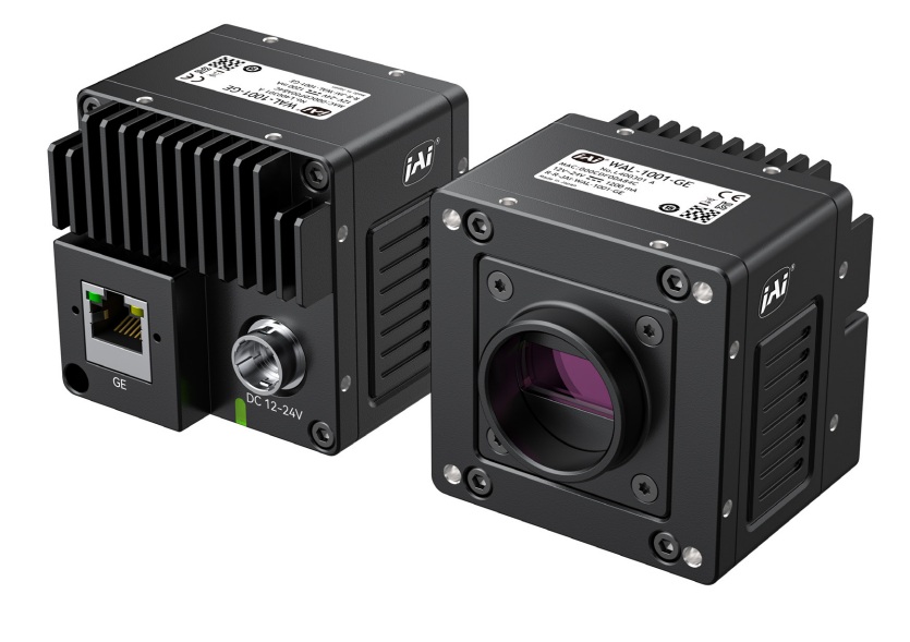
Wave WAA-1300-GE-TEC SWIR camera – Courtesy JAI

Applications

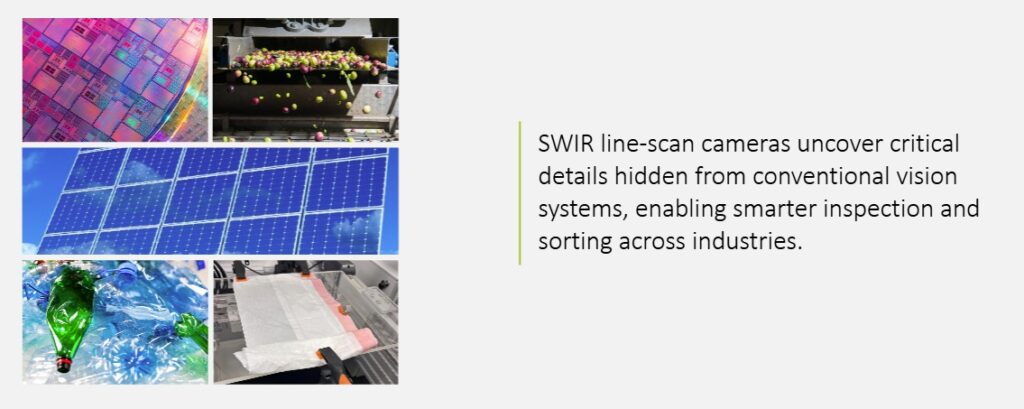
Semiconductor alignment:

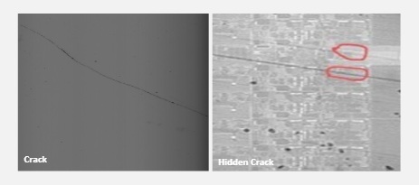
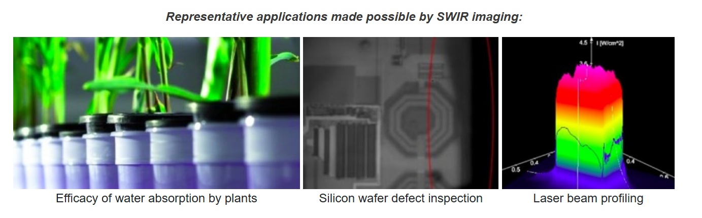
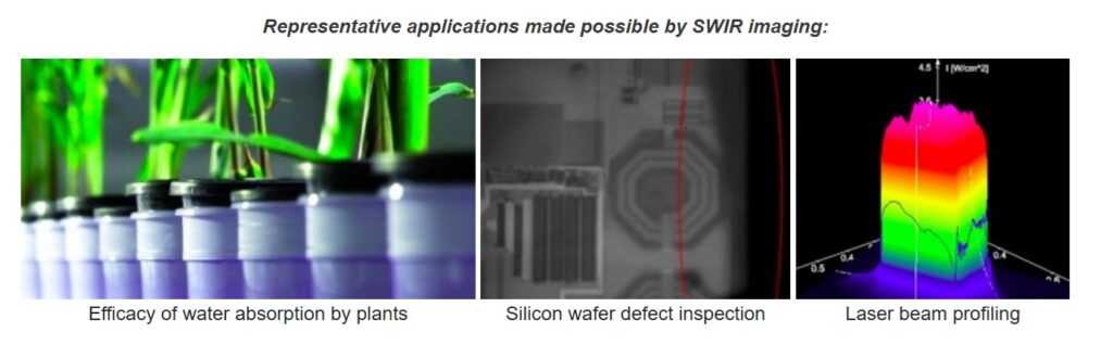
SWIR sees through silicon layers to find alignment marks. This enables precision through successive process layers. Image courtesy of JAI.


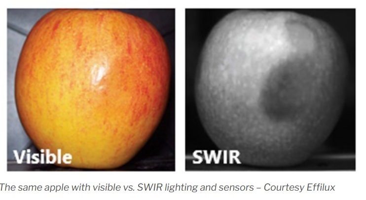
Fruit and vegetable sorting:

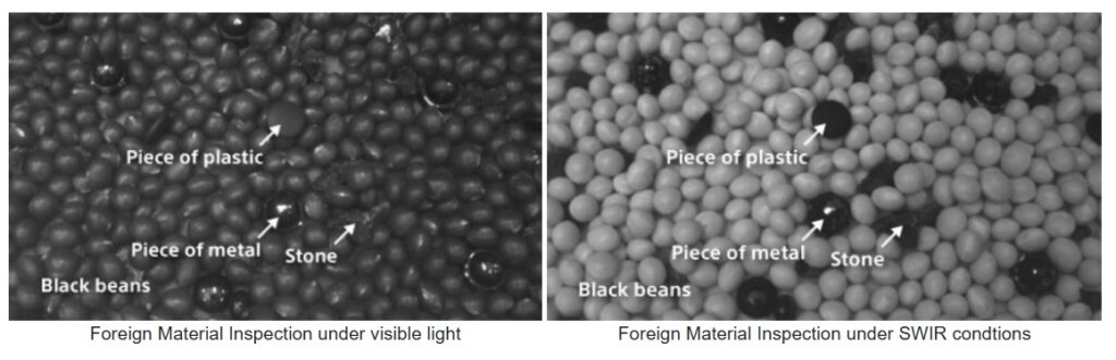
VIS + SWIR working together can identify bruising, ripeness levels, early spoilage, and more. Image courtesy of JAI.


Laser beam profiling:

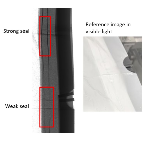
SWIR enables measuring beam shape, intensity distribution, and alignment. Image courtesy of JAI.


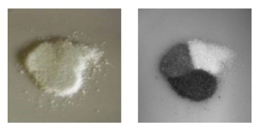
Recycling and material sorting:

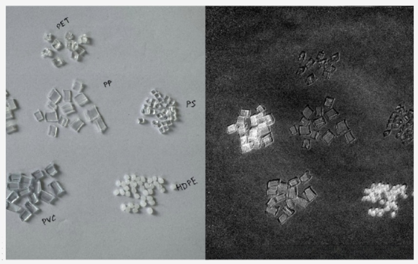
In VIS two clear plastic bottles might appear the same, but SWIR can see their different response in it’s portion of the spectrum – allowing different handling. SWIR enables measuring beam shape, intensity distribution, and alignment. Image courtesy of JAI.


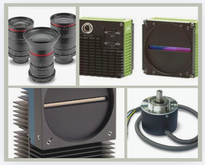
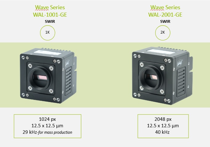
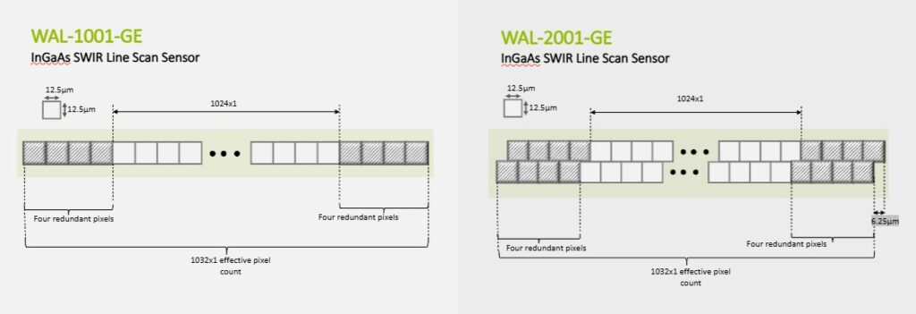
Some of the key Wave WAA-1300-GE-TEC VIS SWIR features – Courtesy JAI

Utilize diverse spectral responses to your advantage

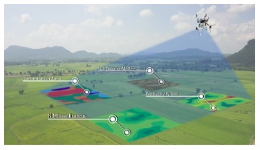
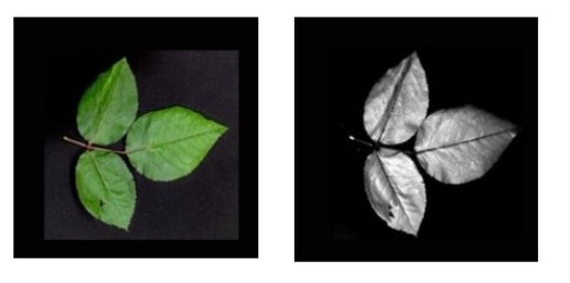
The application areas above are just representative, and are not meant to be exhaustive. The key point is that diverse materials provide differing spectral responses under appropriate light (including natural light).

Applications may be designed to identify and differentiate materials according to their spectral properties. Sensors, cameras, lighting, and lenses are available for machine vision applications that draw upon each of UV, VIS, IR, NIR, SWIR, MWIR, and LWIR portions of the spectrum. And combinations thereof – like the VisSWIR JAI Wave WAA-1300-GE-TEC.


1st Vision’s sales engineers have over 100 years of combined experience to assist in your camera and components selection.  With a large portfolio of cameraslensescablesNIC cards and industrial computers, we can provide a full vision solution!

About you: We want to hear from you!  We’ve built our brand on our know-how and like to educate the marketplace on imaging technology topics…  What would you like to hear about?… Drop a line to info@1stvision.com with what topics you’d like to know more about.

#TEC

#VISSWIR

#JAI

Allied Vision HR high-resolution RF and T models

HR decodes pretty readily to high-resolution. In this series that ranges from 16 MP through 105 MP. There are a range of interfaces available. And many shared features such as advanced image correction: lens shading, defect pixel correction, and low-noise image acquisition.

One member of the Allied Vision HR camera series – Courtesy Allied Vision

It’s NOT the point of this short article to cover the entire HR series.

Our focus is on two particular features available on certain members of the HR series, each of which brings something special.

HR RF Mount models feature a native Canon RF mount, enabling the use of Canon RF lenses for large-format imaging applications requiring high-performance optics and a wide range of focal lengths.

HR T (TEC) models feature thermoelectric cooling and heating (TEC) to regulate sensor temperature. Maintaining a stable sensor temperature helps reduce dark current, thermal noise, and sensor drift while improving image consistency for long exposure, scientific imaging, and precision inspection applications.


HR RF mount characteristics

The RF mount introduced optical, electronic, and economic benefits.

Optics: Per Canon, “RF lenses can be constructed with larger diameter, rear-positioned elements. This type of design helps reduce the bending of light rays as they pass through the lens, which reduces aberrations and improves overall image quality. It is now possible to have larger apertures for a given focal length and achieve corner-to-corner sharpness with minimal light fall-off.”

The large diameter and short back focus distance of the RF mount makes it possible to position lens elements nearer the focusing plane and achieve greater freedom in optical design. Courtesy Canon

Electronics: The RF mount has a 12-pin connection between the camera and lens. This enables much fast communication between lens and camera, and with bandwidth for data transfer.  Software may control a variety of settings such as shutter speed, aperture, exposure compensation.

Another benefit is in-camera correction of optical aberrations and real-time Digital Lens Optimisation (DLO). DLO data is stored within RF lenses and can be read automatically.

Economics: Because the mount covers a wide range of focal lengths, but with a short 20 mm flange distance, the lenses may be made more compact and lightweight. This reduces materials and production costs, a benefit that can be passed to the buyer.


HR T TEC model characteristics

Thermoelectric cooling (TEC) uses the Peltier-Seebeck effect to transport the heat from the main board of the camera to the housing, thereby cooling the mainboard and improving efficiency of the camera sensors by reducing dark current. When the mainboard heats up during operation, a difference in voltage will build up between the housing and the mainboard.

As a result, the mainboard is cooled whereas the housing gets warmer. The housing then dissipates the heat to the surroundings.

Front and rear views of one HR T camera model – Courtesy Allied Vision

The settings for the Device Temperature Selector can be used to monitor the hardware temperature of the main board, the power supply, the FPGA, and the sensor during operation.

The advanced housing design, equipped with integrated ventilation, facilitates a temperature differential of up to 15°C between the camera housing and the sensor. This is the basis for optimal sensor temperature conditions.


1st Vision’s sales engineers have over 100 years of combined experience to assist in your camera and components selection.  With a large portfolio of cameraslensescablesNIC cards and industrial computers, we can provide a full vision solution!

About you: We want to hear from you!  We’ve built our brand on our know-how and like to educate the marketplace on imaging technology topics…  What would you like to hear about?… Drop a line to info@1stvision.com with what topics you’d like to know more about.

#AlliedVision

#HRhighresolution

#CanonRFmount

#TEC

Allied Vision FXO cameras to 100GigE and 671fps

Allied Vision FXO cameras are high-speed industrial GigE Vision cameras available with 10GigE, 25GigE, and 100GigE interfaces. Built around Sony Pregius S global shutter sensors, FXO cameras deliver high image quality, fast frame rates, low-latency image transfer, and reliable performance for demanding machine vision applications.

FXO 100 GigE cameras – Courtesy Allied Vision

Stable data for high-throughput metrology, semiconductor and industrial inspection

In semiconductor and electronics manufacturing, the FXO 100GigE cameras are suited for high-throughput 2D and 3D automated optical inspection because the global shutter supports fast motion without distortion and RDMA-based transport keeps data movement consistent under heavy loads.

In addition to metrology and industrial inspection, the FXO cameras are ideal for laser triangulation, 3D scanning and high-speed acquisition.

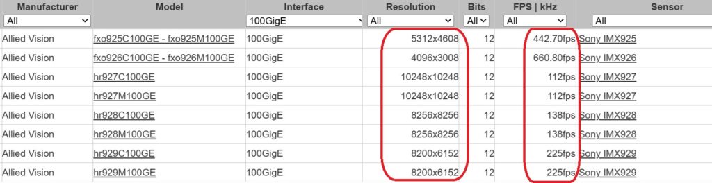
FXO 100GigE models at a glance – Courtesy Allied Vision

SVS-Vistek FXO cameras now part of Allied Vision – Courtesy Allied Vision

10, 25 and 100GigE FXO cameras

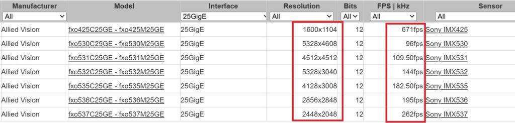
While the 100GigE models are the newest to join the product family, your application’s demands might be satisfied with 10GigE or 25GigE models. Even “just” the 10GigE models offer frame rates from 30 – 217fps, depending on sensor. Likewise the 25GigE models span 96 – 671fps. You wouldn’t be fishing in this pond unless framerate was a factor, but as with any engineering challenge, it’s the overall solution and fit that matters.

Click to contact
Give us a brief idea of your application – we will contact you to discuss options.

RDMA note

RDMA (Remote Direct Memory Access) enables the host PC to directly access camera memory, avoiding memory copy to readout buffers, operating system overhead (time) costs, or CPU load. Special network adapters are required to support RDMA. But for demanding applications, where sustained high framerates are required, without missing data, RDMA can provide low-latency throughput.

Within the FXO family, all the 100GigE cameras support RDMA, and selected models of the 25GigE cameras offer RDMA. It’s not needed on the 10GigE models.

We have a blog on RDMA if you want to dive a bit deeper on your own.

About those network adapters

Unless you are new to machine vision, you already have some experience with network adapters aka NICs or network interface controller (or cards). They come in various flavors, according to PC host bus architecture, port count, protocol, bandwidth capacity, and budget.

For the Allied Vision FXO cameras, see suggested NICs according to camera model and throughput:

Plus a pair of transceivers

When using an RDMA camera model with fiber optic cable, you’ll also need a transceiver at both the camera and the PC host:

Key components for an RDMA data networking configuration – Courtesy Allied Vision

Transceiver: QFSP28 – you need on for each end, per diagram above


FXO camera highlights

Sony Pregius S sensors – Yes we mentioned it already above, but it bears repeating. These backlit sensors are highly sensitive, low noise, and with small pixel sizes.

Color, monochrome, and SWIR model options – while it’s common to find the color/mono options in the same product line, the SWIR option is rather distinctive. It creates potential efficiencies for multi-spectral applications.

Long cable runs to multi-kilometer distancesQSFP28 (Quad Small Form-factor Pluggable) interface enables distances up to multiple kilometers between your PC host and the camera, via fiber.

Advanced thermal design – dissipates heat effectively to maintain low noise high-quality images.


Does your application require 25 or 100 GigE bandwidth to sustain your target image sizes and framerates? Start with application requirements and work back to sensor, camera, interface, cabling, etc. We’re here to help.

1st Vision’s sales engineers have over 100 years of combined experience to assist in your camera and components selection.  With a large portfolio of cameraslensescablesNIC cards and industrial computers, we can provide a full vision solution!

About you: We want to hear from you!  We’ve built our brand on our know-how and like to educate the marketplace on imaging technology topics…  What would you like to hear about?… Drop a line to info@1stvision.com with what topics you’d like to know more about.

#AlliedVision

#FXO

#100GigE

#Machinevision

What is RDMA?

Remote Direct Memory Access – RDMA – is a data transfer method supporting greater throughput compared to traditional transfer methods. While it’s been used in data centers and by networking innovators for some years, it’s only recently been made available for machine vision.

In a phrase: RDMA is a method of transferring data directly between a device and a designated area of computer memory with little involvement from the operating system and CPU.

Some image transfer context to motivate the need for RDMA

Cameras doing real time machine vision don’t send entire images in a single file – it’s not like jpg images from a smartphone. Rather, sensor data is read out in pixel values conveyed in bytes in turn assembled into packets. The operating system, CPU, and networking protocol move the packets and assemble the image in the PC host.

At “conventional” GigE speeds like 1GigE, 5GigE, and 10GigE, a regular NIC and your PC host processor can typically keep up with the framerates flowing from the camera to the PC and vision application software.

But at 25GigE and especially 100GigE, which you may need for your high framerate application, the CPU might get so overwhelmed with data copy and network protocol management that not enough CPU cycles remain for image processing per se. Which in turn risks frame loss and latency bottlenecks.

An analogy

Suppose a package has to get to a specific recipient’s desk in a mid-town office building or on a large industrial campus with multiple buildings and departments. One method would be to get it from the external shipper to a receiving department. Who then transport it to the department level. Who then get it to the business unit. And finally to the intended individual. It works. But it’s a lot of handling, each of which has a cost in labor and time and hence efficiency. That’s equivalent to the traditional network packetization and delivery approach.

The RDMA-equivalent approach would be to authorize the external delivery service (once suitably credentialed) to deliver the parcel directly to the intended desktop, without all the intermediate handling steps.

RDMA at a glance

Recall that GigE Vision utilizes GVSP – GigE Vision Streaming Protocol. Which in turn depends on UDP – User Datagram Protocol. Which is built on top of network layer IP – Internet Protocol. GigE Vision 3.0 added an RDMA-based streaming option, GVRSP, for applications that need higher data rates and less CPU overhead.

Translating that into conventional GigE data transfer, there are typically the four layers shown in the left-hand side of the diagram below: Application, Socket, Transfer Protocol, and Driver level. All those are abstracted away from the user/programmer by your GigE Vision compliant camera, NIC, and SDK – but the layers are all in there. And the successive handoffs between the layers, at both the transmission and receiving side, require communications handoffs and data buffering. Which incurs performance costs in time as well as processor load.

Reduce number of handling instances with RDMA increases throughput – Courtesy Allied Vision

Reduced buffering and handoffs with RDMA

Now look at the right-hand side of the diagram above, utilizing RDMA. Three handoff and two buffering layers are bypassed, yielding substantial throughput gains. Just as with traditional GigE Vision, the user/programmer does not have to manage data transport. Your device manufacturers and SDK provider take of that for you. But you get to harvest the performance gains.

Zero-copy

As you get into RDMA, you may see the “zero-copy” characteristic touted as a benefit. Don’t be confused by the term “copy”. It doesn’t mean conventional networking makes duplicate copies. Merely that conventional networking has to move a packet from one buffer to another, so it copies to the new and releases the old. It’s the “reduced handling instances” concept illustrated in the diagram above.

Key benefits

Higher sustained throughput – host PC doesn’t get bogged down

Lower CPU utilization – frees up capacity for image processing

Lower latency and jitter – image delivery faster and regularized

Improved stability – avoids dropped packets or frames

Putting the pieces together

If your application requires the performance delivered by RDMA, despite being a GigE protocol, one uses fiber cables instead of conventional Cat6 ethernet cables. One must convert between copper and glass fiber transmission modes at both the transmission and receiving ends. Hence the transceivers as shown in the illustration below.

Key components for a machine vision RDMA setup – Courtesy Allied Vision

Click to contact
Give us some brief idea of your application and we will contact you to discuss camera and cabling options.

How long a fiber run do you need?

There are transceivers designed for several different throughput and cable length requirements. Costs scale accordingly. But innovative machine vision solutions that bring competitive advantage can drive revenue or reduce other costs, so it’s partly about engineering possibilities and partly about cost : benefit calculation.

Transceivers for different bandwidth and cable length requirements – Courtesy Allied Vision

Note: the multi-km cable lengths are a benefit of fiber optics, not of RDMA per se. It’s a happy coincidence that RDMA performance at 25 and 100GigE is best supported by fiber optics; and that once a signal is on fiber, and can be reliably transmitted a long distance.


Do you need 25 or 100 GigE? Fiber optic cables? RDMA? Start with required application outcomes in terms of image characteristics and framerate, and work back to sensor, camera, interface, and techniques. We do that.

1st Vision’s sales engineers have over 100 years of combined experience to assist in your camera and components selection.  With a large portfolio of cameraslensescablesNIC cards and industrial computers, we can provide a full vision solution!

About you: We want to hear from you!  We’ve built our brand on our know-how and like to educate the marketplace on imaging technology topics…  What would you like to hear about?… Drop a line to info@1stvision.com with what topics you’d like to know more about.

#RDMA

#Remotedirectmemoryaccess