Sony STARVIS 2 sensors in IDS Imaging uEye cameras

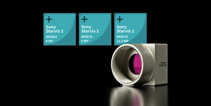
Sony has evolved their successful STARVIS high-sensitivity back-illuminated sensor to the next generation STARVIS 2 sensors. This brings even wider dynamic range, and is available in three specific resolutions of 4MP, 5MP, and 12.5MP. The sensor models are respectively Sony IMX664, IMX675, and IMX676. And IDS Imaging has in turn put these sensors into their uEye cameras.

uEye USB3 C-mount camera available with any of the three Sony STARVIS 2 sensors – Courtesy IDS Imaging

Camera overview before deeper dive on the sensors

The new sensors, responsive in low ambient light to both visible and NIR, are available in IDS’ compact, cost-effective uEye XCP and uEye XLS cameras. They’re available in both the XCP housed cameras with C-mount optics and USB3 interface. And in the XLS board-level format with C/CS, S, and no-mount options, also with the USB3 interface

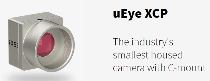
Choose the XCP models if you want the closed zinc die-cast housing, the screwable USB micro-B connector, and the C-mount lens adaptor for use with a wide range of multi-megapixel lenses. Digital I/O connections plus trigger and flash pins may also be connected.

uEye XCP – Courtesy IDS Imaging

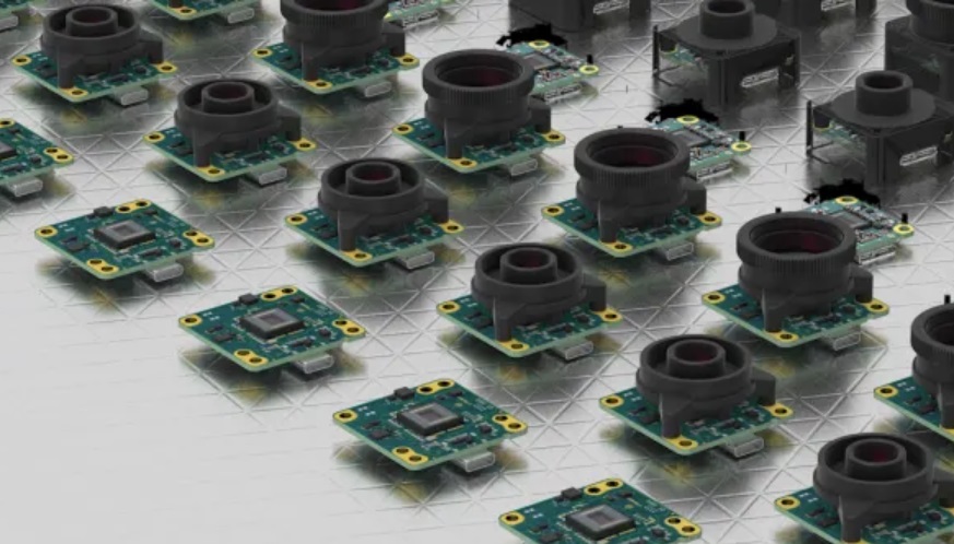
If you prefer a board-level camera for embedded designs, and even lower weight (from 3 – 20 grams) select one of the XLS formats. Options include C/CS and S-mount, or no-mount.

XLS board level models – Courtesy IDS Imaging

All models across both camera families are Vision Standard compliant: U3V / GenICam. So you may use the IDS Peak SDK. Or any other compliant software.

Deeper dive on the sensors themselves

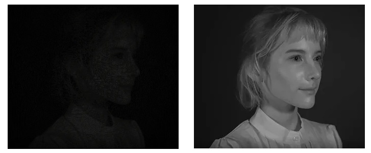
To motivate the technical discussion, let’s start with side-by-side images, only one of which was obtained with a STARVIS 2 sensor:

Left image with IMX236; right image with Sony IMX585 STARVIS 2 sensor – Courtesy Sony.

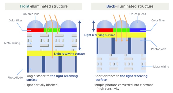
How is such a dramatic improvement possible, over Sony’s earlier sensors? The key is switching from traditional front-illuminated sensors to STARVIS’ back-illuminated design. The back-illuminated approach collects more incident light – by a factor of 4.6 times – by positioning the photo diodes on top of the wiring layer.

Substantially more light makes it to the photo diodes using back-illumination architecture – Courtesy Sony

See also a compelling 4 minute video showing images and streaming segments generated with and without STARVIS 2 sensors.

NIR as well as VIS sensitivity

The STARVIS 2 sensors are capable of not only conventional visible spectrum performance (VIS), but also do well in the NIR space. If the subject’s NIR sensitivity is sufficient, one may avoid or reduce the need for supplemental NIR lighting. This is useful for license plate recognition applications, security, or other uses where lighting in certain spectra or intensities would disturb humans.

Left image from sensor with no NIR response; right image with STARVIS 2 sensor – Courtesy Sony.

Performance and feature highlights

The 4 MP Sony IMX664 delivers up to 48.0 fps, at 2688 x 1536 pixels, with USB3 delivering 5 Gbps. It pairs with lenses matched for up to 1/1.8″.

Sony’s IMX675, with 2592 x 1960 pixels, provides 5 MP at frame rates to 40.0 fps, via the same USB3 interface.

Finally, the 12.62 MP Sony IMX676,is ideal for microscopy with square format 3552 x 3552, but can still deliver up to 17.0 fps for applications with limited motion.

While there are diverse sensor features to explore in the data sheets for both the uEye XCP and uEye XLS cameras, one particularly worth noting is the High Dynamic Range (HDR) feature. These feature controls are made available in the camera, permitting bright scene segments to experience short exposures, while darker segments get longer exposure. This yields a more actionable dynamic range for your application to process.

No HDR in left image; with HDR feature enabled in right image – Courtesy Sony.

Direct links to the cameras

In the table below one finds each camera by model number, family, and sensor, with link to respective landing page for full details, spec sheets, etc.

ModelFamilySensor
U3-34E0XCPuEye XCP housedSONY IMX664
U3-34F0XCPuEye XCP housedSONY IMX675
U3-34L0XCPuEye XCP housedSONY IMX676
U3-34E1XLSuEye XLS boardSONY IMX664
U3-34F1XLSuEye XLS boardSONY IMX675
U3-34L2XLSuEye XLS boardSONY IMX676
IDS Imaging uEye housed and board-level cameras with Sony STARVIS 2 sensors

1st Vision’s sales engineers have over 100 years of combined experience to assist in your camera and components selection.  With a large portfolio of cameraslensescablesNIC cards and industrial computers, we can provide a full vision solution!

About you: We want to hear from you!  We’ve built our brand on our know-how and like to educate the marketplace on imaging technology topics…  What would you like to hear about?… Drop a line to info@1stvision.com with what topics you’d like to know more about.
Opto Engineering HC 360° Hypercentric 360°Lenses

Inspect the inner sides and bottom of hollow objects simultaneously with Opto Engineering’s HC 360° hypercentric lenses.

HC 360° hypercentric lenses – Courtesy Opto Engineering

The optical path of the rays pass through the narrow openings of hollow objects (pipes, bottles, cans, vials, etc.) without the need to rotate an object, use a probe, or use multi-camera configurations. HC hypercentric lenses are used in diverse inspection applications including beverage, pharmaceutical, and cosmetics industries.

Courtesy Opto Engineering

See landing page for all 8 members of the Opto Engineering HC family

…including part number, image circle size and sensor pairings, FOV, and spec sheet links. And corresponding quote-request links.

Example of a glass bottle inspections with HCSI lens – Courtesy Opto Engineering
Contact us for a quote

IF one didn’t know about 360° hypercentric lenses…

… one might attempt a muti-camera or line scan solution. But there are drawbacks to each of those approaches.

Drawbacks of a multicamera solution – Courtesy Opto Engineering

OK, what about linescan? Linescan is know to be good for high resolution images of elongated objects. Yes, but one would need a separate camera for each of the sides vs. the bottom of the object. Most significant, however, is the requirement for motion essential to a linescan design, as the camera or object must rotate to expose all “slices”, while the object is concurrently progressing down the line.

Linescan continuous motion requirement not compatible with 360° view requirement – Courtesy Opto Engineering

Opto Engineering 360° lenses check all the boxes

Since line scan really isn’t a solution, and a multicamera approach is complex at best, for comprehensive inspection of the inner sides and bottom of hollow objects, these Opto Engineering 360° lenses offer an attractive solution.

Pros and cons of different approaches when 360° view is required – Courtesy Opto Engineering

1st Vision’s sales engineers have over 100 years of combined experience to assist in your camera and components selection.  With a large portfolio of cameraslensescablesNIC cards and industrial computers, we can provide a full vision solution!

See these other blogs on Opto products!

About you: We want to hear from you!  We’ve built our brand on our know-how and like to educate the marketplace on imaging technology topics…  What would you like to hear about?… Drop a line to info@1stvision.com with what topics you’d like to know more about.
FPD-Link III vs GMSL2 vs CSI-2 vs USB considerations for deployment

New interface options arrive so frequently that trying to keep up can feel like drinking water from a fire hose. While data transfer rates are often the first characteristic identified for each interface, it’s important to also note distance capabilities, power requirements, EMI reduction, and cost.

Which interfaces are we talking about here?

This piece is NOT about GigE Vision or Camera Link. Those are both great interfaces suitable for medium to long-haul distances, are well-understood in the industry, and don’t require any new explaining at this point.

We’re talking about embedded and short-haul interface considerations

Before we define and compare the interfaces, what’s the motivation? Declining component costs and rising performance are driving innovative vision applications such as driver assistance cameras and other embedded vision systems. There is “crossover” from formerly specialized technologies into machine vision, with new camera families and capabilities, and it’s worth understanding the options.

Alvium camera with FPD-Link or GMSL interface – Courtesy Allied Vision Technologies

How shall we get a handle on all this?

Each interface has standards committees, manufacturers, volumes of documentation, conferences, and catalogs behind it. One could go deep on any of this. But this is meant to be an introduction and overview, so we take the following approach.

  • Let’s identify each of the 4 interfaces by name, acronym, and a few characteristics
  • While some of the links jump to a specific standard’s full evolution (e.g. FPD-Link including Gen 1, 2, and 3), per the blog header it’s the current standards as of Fall 2024 that are compelling for machine vision applications: CSI-2, GMSL2, and FPD-Link III, respectively
  • Then we compare and contrast, with a focus on rules of thumb and practical guidance

If at any point you’ve had enough reading and prefer to just talk it through:

FPD-Link III – Flat Panel Display Link

A free and open standard, FPD-Link has classically been used to connect a graphics display unit (GPU) to a laptop screen, LCD TV, or similar display.

FPD-Link automotive applications schematic – Courtesy Texas Instruments

FPD-Link has subsequently become widely adopted in the automotive industry, for backup cameras, navigation systems, and driver-assistance systems. FPD-Link exceeds the automotive standards for temperature ranges and electrical transients, making it attractive for harsh environments. That’s why it’s interesting for embedded machine vision too.

GMSL2 – Gigabit Multimedia Serial Link

GMSL – Courtesy Analog Devices

GMSL is widely used for video distribution in cars. It is an asymmetric full duplex technology. Asymmetric in that it’s designed to move larger volumes of data downstream, and smaller volumes upstream. Plus power and control data, bi-directionally. Cable length can be up to 15m.

CSI-2 – Camera Serial Interface (Gen. 2)

CSI-2 registered logo – Courtesy mipi alliance

As the Mobile Industry Processor Interface (MIPI) standard for communications between a camera and host processor, CSI-2 is the sweet spot for applications in the CSI standards. CSI-2 is attractive for low power requirements and low electromagnetic interference (EMI). Cable length is limited to about 0.5m between camera and processor.

USB – USB3 Vision

USB3 Vision registered logo – Courtesy Association for Advancing Automation

USB3 Vision is an imaging standard for industrial cameras, built on top of USB 3.0. USB3 Vision has the same plug-and-play characteristics of GigE Vision, including power over the cable, and GenICam compliance. Passive cable lengths are supported up to 5m (greater distances with active cables).

Compare and contrast

In the spirit of keeping this piece as a blog, in this compare-and-contrast segment we call out some highlights and rules-of-thumb. That, together with engaging us in dialogue, may well be enough guidance to help most users find the right interface for your application. Our business is based upon adding value through our deep knowledge of machine vision cameras, interfaces, software, cables, lighting, lensing, and applications.

CABLE LENGTHS COMPARED(*):

  • CSI-2 is limited to 0.5m
  • USB3 Vision passive cables to 5m
  • FPD-Link distances may be up to 10m
  • GMSL cables may be up to 15m

(*) The above guidance is rule-of-thumb. There can be variances between manufacturers, system setup, and intended use, so check with us for an overall design consultation. There is no cost to you – our sales engineers are engineers first and foremost.

BANDWIDTH COMPARED#:

  • USB3 to 3.6 Gb/sec
  • FPD-Link to 4.26 Gb/sec
  • GMSL to 6 Gb/sec
  • CSI-2 to 10 Gb/sec

(#) Bandwidth can also vary by manufacturer and configuration, especially for MIPI and SerDes [SerializerDeserializer], and per chipset choices. Check with us for details before finalizing your choices.

RULES OF THUMB:

  • CSI-2 often ideal if you are building your own instrument(s) with short cable length
  • USB3 is also good for building one’s own instruments when longer distances are needed
  • FPD-Link has great EMI characteristics
  • GMSL is also a good choice for EMI performance
  • IF torn between FPD-Link vs. GMSL, note that there are more devices in the GMSL universe, so that might skew towards easier sourcing for other components

1st Vision’s sales engineers have over 100 years of combined experience to assist in your camera and components selection.  With a large portfolio of cameraslensescablesNIC cards and industrial computers, we can provide a full vision solution!

About you: We want to hear from you!  We’ve built our brand on our know-how and like to educate the marketplace on imaging technology topics…  What would you like to hear about?… Drop a line to info@1stvision.com with what topics you’d like to know more about.
New Alvium cameras with Sony SenSWIR InGaAs sensors

Short Wave Infrared (SWIR) imaging enables applications in a segment of the electromagnetic spectrum we can’t see with the human eye – or traditional CMOS sensors. See our whitepaper on SWIR camera concepts, functionality, and application fields.

Until recently, SWIR imaging tended to require bulky cameras, sometimes with cooling, which were not inexpensive. Cost-benefit analysis still justified such cameras for certain applications, but made it challenging to conceive of high-volume or embedded systems designs.

Enter Sony’s IMX992/993 SenSWIR InGaAs sensors. Now in Allied Vision Technologies’ Alvium camera families. These sensors “see” both SWIR and visible portions of the spectrum. So deploy them for SWIR alone – as capable, compact, cost-effective SWIR cameras. Or you can design applications that benefit from both visible and SWIR images.

Alvium configuration and interface options – Courtesy Allied Vision Technologies

Camera models and options first

The same two sensors, both the 5.3 MP Sony IMX992 and the 3.2 MP Sony IMX993, are available in the Allied Vision Alvium 1800 series with USB3 or MIPI CSI-2 interfaces. As well as in the Alvium G5 series with 5GigE interfaces.

And per the Alvium Flex option, besides the housed presentation available for all 3 interfaces, both the USB3 and CSI-2 versions may be ordered with bare board or open-back configuration, ideal for embedded designs.

Broken out by part number the camera models are:

More about the Sony IMX992 / IMX993 sensors

The big brother IMX992 at 5.3 MP and sibling IMX993 at 3.2 MP share the same underlying design and features. Both have 3.45 µm square pixels. Both are sensitive across a wide spectral range from 400 nm – 1700 nm with impressive quantum efficiencies. Both provide high frame rates – to 84 fps for the 5.3 MP camera, and to 125 fps at 3.2 MP.

Distinctive features HCG and DRRS

Sony provides numerous sensor features to the camera designer, which Allied Vision in turn makes available to the user. Two new features of note include High-Conversion-Gain (HCG) and Dual-Read-Rolling-Shutter (DRRS). Consider the images below, to best understand these capabilities:

Illustrating the benefits of HCG and DRRS modes – Courtesy Sony

With the small pixel size of 3.45 µm, an asset in terms of compact sensor size, Sony innovated noise control features to enhance image quality. Consider the three images above.

The leftmost was made with Sony’s previously-released IMX990. It’s been a popular sensor and it’s still suitable for certain applications. But it doesn’t have the HCG nor DRRS features,

The center image utilized the IMX992 High-Conversion-Gain feature. HCG reduces noise by amplifying the signal immediately after light is converted to an electrical signal. This is ideal when shooting in dark conditions. In bright conditions one may use Low-Conversion-Gain (LCG), essentially “normal” mode.

The rightmost image was generated using Dual-Read-Rolling-Shutter mode in addition to HCG. DRRS mode delivers a pair of images. The first contains the imaging signal together with the embedded noise. The second contains just the noise components. The camera designer can subtract the latter from the former to deliver a synthesized image with approximately 3/4 of the noise eliminated.

Alvium’s SWaP+C characteristics ideal for OEM systems

With small Size, low Weight, low Power requirements, and low Cost, Alvium SWIR cameras fit the SWaP+C requirements. OEM system builders need or value each of those characteristics to build cost-effective embedded and machine vision systems.

1st Vision’s sales engineers have over 100 years of combined experience to assist in your camera and components selection.  With a large portfolio of cameraslensescablesNIC cards and industrial computers, we can provide a full vision solution!

About you: We want to hear from you!  We’ve built our brand on our know-how and like to educate the marketplace on imaging technology topics…  What would you like to hear about?… Drop a line to info@1stvision.com with what topics you’d like to know more about