Multifield imaging is a new imaging technology that enables capturing multiple images simultaneously at various lighting conditions e.g. brightfield, darkfield, and backlight in a single scan. It’s a variation on the concept of sequence modes. Teledyne Dalsa Linea HS is the industry’s first TDI camera capable of capturing up to three images using light sources at different wavelengths.
OK, cool. How does that help me? How does it differ from other imaging methods? What applications can it solve that couldn’t be tackled before?
Perhaps a quick review of area scan imaging and conventional linescan imaging will help set the stage:
Area scan cameras are most intuitive, creating in one exposure a rectangular array of pixels corresponding to an entire scene or field of view.T hat’s ideal for many types of machine vision imaging, if the target fits wholly in the field of view, and if the lighting, lens, and image processing can best achieve the desired outcome at an optimal price point.
But linescan imaging is sometimes a better choice, especially for continuous-flow applications, where there is no discrete start and end point, in one dimension. Linescan systems can capture an image “slice” that is enough pixels wide to make effective imaging computations, and, where required, to archive those images, using fewer active pixels and reducing sensor costs compared to area scan. Other benefits include high sensitivity and the ability to image fast moving materials without the need for expensive strobe lighting.
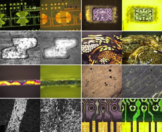
… so much for the review session. So, what can multifield linescan imaging do for me? Multifield capable linescan cameras bring all the benefits of conventional linescan imaging, but additionally deliver the perspectives of monochrome, HDR, color/multispectral (NIR), and polarization views. This can enable machine vision solutions not previously possible, or solutions at more attractive price points, for a diverse range of applications.
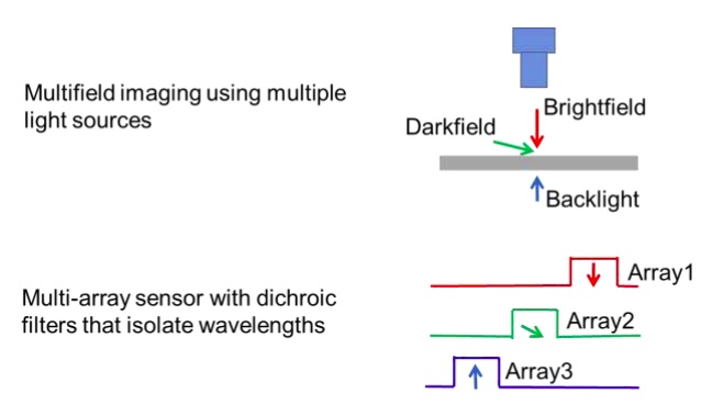
Multifield imaging is a new imaging technology that enables capturing multiple images simultaneously at various lighting conditions e.g. brightfield, darkfield, and backlight in a single scan.
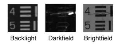
Consider OLED display inspection, for example. Traditionally an automated inspection system would have required multiple passes, one each with backlight, darkfield, and brightfield lighting conditions. With a multifield solution, all three image types may be acquired in a single pass, greatly improving throughput and productivity.
So how is multifield imaging achieved? In this blog we’re more focused on applications. For those new to Time Delay and Integration (TDI), it is the concept of accumulating multiple exposures of the same (moving) object, effectively increasing the integration time available to collect incident light. The key technology for a multifield linescan camera is the sensor uses advanced wafer-level coated dichroic filters with minimum spectral crosstalk to spectrally isolate three images captured by separate TDI arrays, i.e. wavelength division multifield imaging.
This new technology significantly boosts system throughput as it eliminates the need of multiple scans. It also improves detectability as multiple images at different lighting conditions are captured simultaneously with minimum impact from mechanical vibration.
1stVision is pleased to offer our customers a multifield linescan camera from Teledyne Dalsa, the HL-HF-16K13T: https://www.1stvision.com/cameras/models/Teledyne-DALSA/HL-HF-16K13T
Contact 1stVision for support and / or pricing.

Give us some brief idea of your application and we will contact you to discuss camera options.
1st Vision’s sales engineers have an average of 20 years experience to assist in your camera selection. Representing the largest portfolio of industry leading brands in imaging components, we can help you design the optimal vision solution for your application.