Machine vision camera and lens selection tools including educational resources

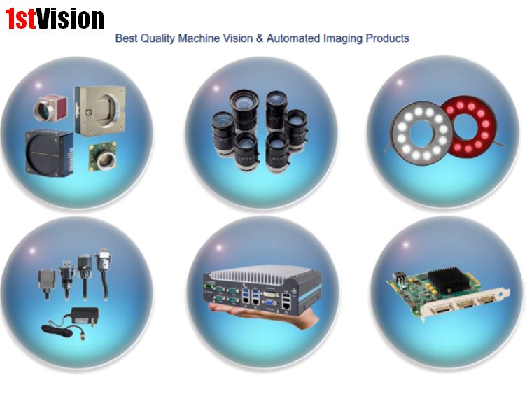
1stvision industrial imaging components
Click on this picture to visit the new site now!

1stVision is making it easier in selecting industrial imaging components!   We have introduced new  machine vision camera and lens selector tools in our new website in addition to our educational resources.

5 ways to help in your industrial imaging selection are below:

  • Industrial machine vision camera selector:  Sort by manufacturer, interface, resolution, image sensor and image format to name a few.
  • Machine Vision lens selector:  Sort by manufacturer, focal length, format size, and lens quality
  • Technical Blog:  Posts are published monthly with educational content on cameras, image sensors, lenses along with technical primers and white papers.   The blog is categorized and allows you to search by a topic.
  • Knowledge Base:  This section contains technical articles on cameras, lenses, interfaces, vision standards and several other topics.

Watch our short video showing the key features in helping select cameras and lenses

Our combined staff has over 100 years of experience in the industrial imaging market!   We are well versed in the technical details, down to the camera sensor level and can help ensure the components you select are the best for your application.

Contact us to talk to an expert!

How to get greater resolution from your color sensor using a low cost 18 MP IDS camera

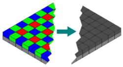
Bayer Patter - Mono
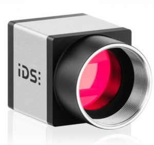
IDS UI-3590 camera
IDS UI-3590CP camera

The AR1820HS Image sensor 18 mega pixel sensor in the IDS Imaging IDS Imaging UI-3590 camera models was launched by the sensor manufacturer ON Semiconductor as a pure color sensor.  Like all color sensors, the Bayer filter means that you get color images with effectively only around a quarter of the nominal sensor resolution, as the color information for each pixel is obtained from four neighbors

To use each individual pixel, however, it is not sufficient to operate the sensor in RAW data format (without Bayer interpolation).  Operating in a raw format results in a different brightness perception of the individual pixels and NOT a usable image.

This technical tip will show you how to use the color sensor as a “pure” mono sensor by appropriate parameter settings and the use of suitable light sources, in order to obtain a significantly higher resolution.

Applications which require a color image and precision will benefit from this camera and method.. and all for less than $600 with the IDS UI-3590LE camera

Background

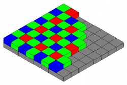
Bayer Pattern
Arrangement of colour filters in the Bayer matrix

The principle of digital image sensors such as the 18 MP ON Semiconductor AR1820HS means that they acquire only brightness, but not color information.

As a result, a color filter is applied to each pixel during manufacture of the color sensors.  This is known as the Bayer matrix.

Of each four pixels, two pixels are given a green color filter, one pixel a red filter and one pixel a blue color filter.  This color distribution corresponds to the perception of the human eye and is referred to as the Bayer matrix.

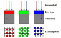
RGB Filter
The RGB filter layers only transmit light with
a particular wavelength

A pixel depicts only the information for one color.

To obtain the complete RGB values for each pixel, the missing primary colors are interpolated from four neighboring pixels using appropriate algorithms. This color interpolation assumes that there are only slight color differences between two adjacent pixels of the same color.  Strictly speaking, a sensor with Bayer matrix therefore has only a quarter of the native sensor resolution

Sensor mono mode

Although the Bayer matrix cannot simply be rendered invisible for mono mode, the following two solutions show how you can achieve the desired result depending on the type of application.

1) For “grey scenes”  (i.e. dark pin on a white background)

If the 18 MP color sensor is to be used in mono mode for achromatic scenes, note that a broad band light source (white light) must still be used. This is because of the sensor’s Bayer matrix.  With this sensor, monochromatic (single color) light would have resulted in the individual pixels transmitting no or less information depending on the wavelength of the light, due to the RGB filter layers used (see Figure 2). This can result in a different brightness perception for the individual pixels. In this case, the RGB enhancement must be calibrated separately for R, G, and B. As a result, you then obtain an identical brightness perception for all pixels as with a mono sensor.

IDS Imaging
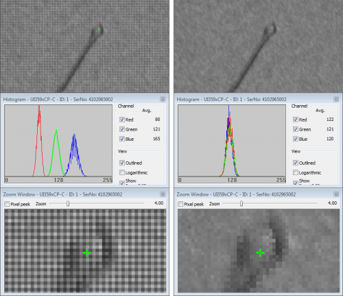
Without calibration of the RGB enhancement, the Bayer matrix is clearly visible (left).
After RGB calibration (see RGB histogram, right) there is a homo-geneous brightness perception as with a mono sensor

Note: This RGB calibration is only valid for this specific light source and a “grey” scene.  If the light source (wavelength) changes, the RGB enhancement factors have to be re-adjusted.

Contact 1stVision to obtain instructions on  switching the Bayer matrix to “invisible” using the uEye Cockpit:2) For “color or grey scenes”

If you work with color scenes in your application, the brightness sensitivity of the individual Bayer pixels constantly changes with the variation in color components. There is also a way to achieve genuine mono mode in this situation. The solution lies in the color spectrum of the 18 MP ON Semiconductor AR1820HS.

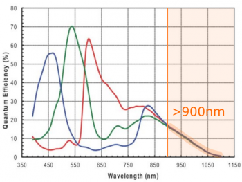
Above a wavelength of around 900 nm the color filters for the individual pixels have similar spectral properties. Beyond this threshold, all pixels on the sensor respond practically identically to incident light again – exactly as with a dedicated mono sensor. This means that the Bayer matrix can also be made invisible using this method, both for color and also for grey scenes

AR1820HS Spectrum
The colour spectrum of the AR1820HS shows similar spectral proper-ties of the colour filters above 900 nm

In order to be able to use this spectral property of the sensor as described, you must observe the following:

  • Ensure defined lighting conditions, i.e. seal off light with other wavelengths shorter than 900 nm as far as possible.
  • Order your uEye camera with AR1820HS sensor specifically with GL filter (glass). The HQ filter normally ordered with this sensor would block out the long-wave light.  By contrast, the GL filter allows light beyond 900 nm to pass with high transmission. The highest possible signal strength thus arrives at the sensor.

Full Information on the IDS Imaging UI-3590LE and UI-3590CP cameras can be found below

IDS-UI-3590LE – 18MP camera, LE version

IDS-UI-3590CP – 18MP camera, CP version

1stVision has over 100 years of industrial imaging experience!  Contact us to help select the best camera and lenses for your applications.

contact us

Dalsa line scan polarization camera makes invisible visible!

Teledyne Dalsa has released the first line scan polarization camera for machine vision.  The Piranha4 polarization camera provides the capability of detecting , stress, surface roughness,  birefringence and physical properties undetectable with conventional imaging making the invisible visible!

This unique technique uses four polarization channels with a color line scan camera solving various applications, but not limited to the following:

Glass Inspection:  Glass bottles, architectural glass sheets, and automobile windshields, etc. – Enables inspection of internal stress and defects non-visible with conventional imaging

Dalsa Polorized ruler

Film inspection: transparent films, packaging films, and patterned films etc. – Detect scratches, digs, and other surface defects that are difficult to detect with conventional imaging   Dalsa Polarized scratch

Precision optics: optical lens, prisms, fibers, and micro-optical – Detect residual internal stress and thermal annealing effects
polarized - stress in sun glasses

Flat Panel Display and PCB inspection: Thin film transistors, organic LEDs, printed circuit boards etc.- inspect ITO, dust particles, films thickness, and surface defects with enhanced contrast

Carbon fibers: effectively inspect the quality of composite materials that are widely used in aircraft, aerospace, wind energy, and automotive industry

Food and material sorting: Increase sorting accuracy and detecting capability of foreign materials such as plastics, glasses, metals etc. with polarization imaging

Bio-medicine: digital pathology, in vitro cells culture, optical coherence tomography etc.- Provides additional information in birefringence tissues
Remote sensing: helps identifying special objects from natural background
And many more…

Contact 1st vision

Line scan polarization camera Features

  • CMOS Quadlinear sensor  – 2048 pixels
  • High speed line rate of 70k hz with 14.08 um pixels
  • Camera Link interface
  • Three polarization states plus and unfiltered channel (Output format with 0 deg (S component), 90 deg (P component), 135 deg and unfiltered polarization states.)

Full specifications on the Teledyne Dalsa polarization camera ( P4-CP-02K07Q-00-R ) can be found HERE

line scan camera Polarization angles

White Paper  – Learn about this unique polarization technique with line scan cameras!   This white paper covers the following topics

  • How polarization techniques work in transmission and reflectance configuration
  • Comparison of three polarization filter technologies
  • How the sensor architecture is configured for polarization effects and visualization of defects.

line scan polarization camera white paper

1stVision has a strong working knowledge of polarization techniques, line scan cameras and lighting and can discuss your application in detail.

Contact us to talk to an expert!

Related Blog posts:
Teledyne Dalsa release of low cost GigE and camera link color line scan cameras

Video Tutorial:  How to setup HDR Imaging in Teledyne Dalsa Linea Line scan cameras

Beware of EMVA 1288 data!

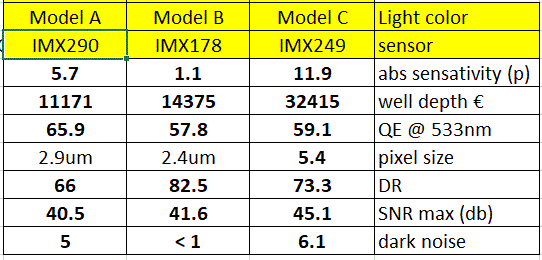
EMVA 1288 dont be scaredMany camera manufacturers are now putting up EMVA 1288 data. This is test suite created by the European Machine Vision Association (EMVA) that give you the characteristics and performance of cameras, e.g. S/N ratio, noise, etc. , and there are specifications on how to run the tests.

Please note that there is a significant amount of variance allowed within the tests.  Each manufacturer has their own test setup, so comparing sensors or product lines from a specific manufacturer is very appropriate.

Comparing results between different manufacturers, especially looking at small details is NOT appropriate.  For instance, if Manufacturer A’s test has a 5% variance on what Manufacturer B’s test is on the same sensor, but the difference between the two manufacturers is 5%, there is no valid conclusion! The result is within the variance.  Do NOT get sucked into this comparison war.

The EMVA test produces a 30 page report for each specific camera test, testing is across multiple wavelengths, etc.  Results that are given in tabular format with one number for each camera are not really a good picture of the test results to compare across manufacturers.

If you want further details, please contact 1stVision.  We have conducted many comparison tests and can provide practical advice and discuss it in context of your application.

Contact us to talk to an expert!

Related Posts

What are the attributes to consider when selecting a camera and its performance