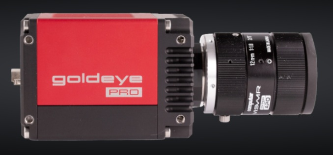
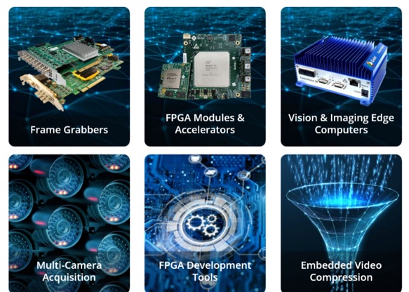
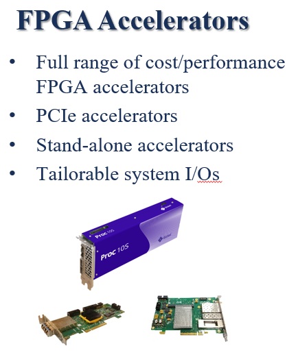
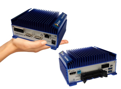
Gidel is a leading provider of high-performance FPGA-based imaging and vision solutions. Their product offerings, engineered for data intensive applications that demand real-time processing and minimal latency, include edge computers powered a Nvidia Jetson™ embedded computer, FPGA-based frame grabbers, recording & streaming systems, and a camera simulator for developing and testing imaging and vision applications. These solutions are available as out-of-the-box, open infrastructure, or fully tailored to your specific application requirements.
Products and features to help with High Dynamic Range
Below we show and describe useful features for applications where High Dynamic Range is needed, but typically are plagued by processing time and image degradation. We explain how Gidel can provide HDR in real time, compress and correct the image for a great image.
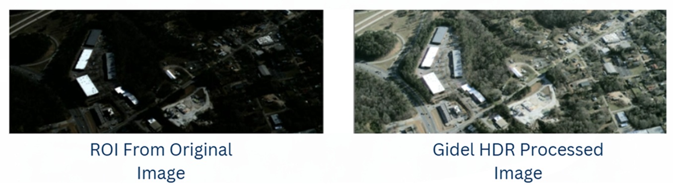
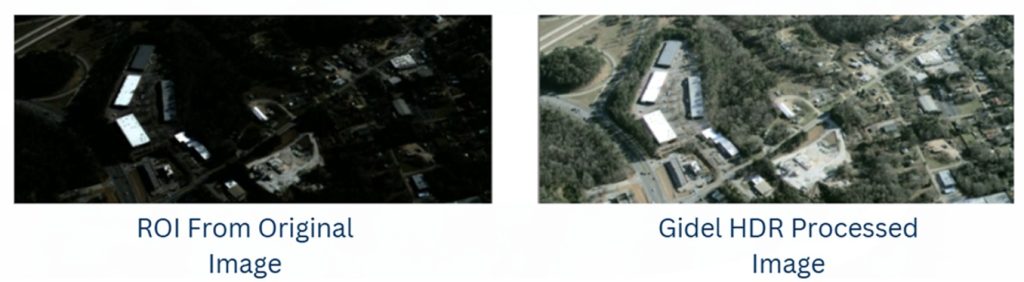
For High Dynamic Range (HDR) context, download our HDR whitepaper for an optional review. And/or let these images motivate the topic:
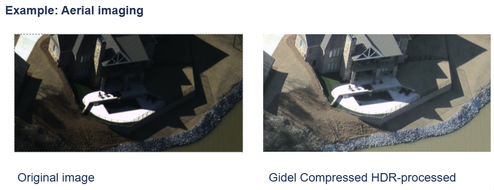
The aerial imaging application is just an example – the principle is widely applicable. They key context for HDR is that many imaging scenes are high-contrast, with deeply nuanced darker regions and equally nuanced brighter regions.
If one controlled for a single-exposure duration across all regions, whether by fixed timing or average pixel saturation, the one-exposure-fits-all image is likely to be a poor or unusable compromise – like the “original image” shown above left. One exposure can’t allow you to see the darks and brights. Either your exposure set to see the dark will saturate the brights… or if you optimize exposure to see the nuanced brights it will make the darks so dark you can’t distinguish them.
For more details on Gidel’s HDR features, see their own features overview and explanations.
At the risk of sounding like an advertisement for laundry detergent about whiter whites and preserving colors, one doesn’t have to dwell on how HDR is achieved to recognize the HDR image shown above right is an improvement over the non-HDR original.
There are other helpful tools besides just HDR
HDR is an often powerful technique to effectively expand the dynamic range of the delivered image. But HDR isn’t always needed, and isn’t always the best tool, whether alone or in combination. Consider also tools and techniques like compression, gamma correction, and white balance – a bit more on each of these below – advantages Gidel can offer.
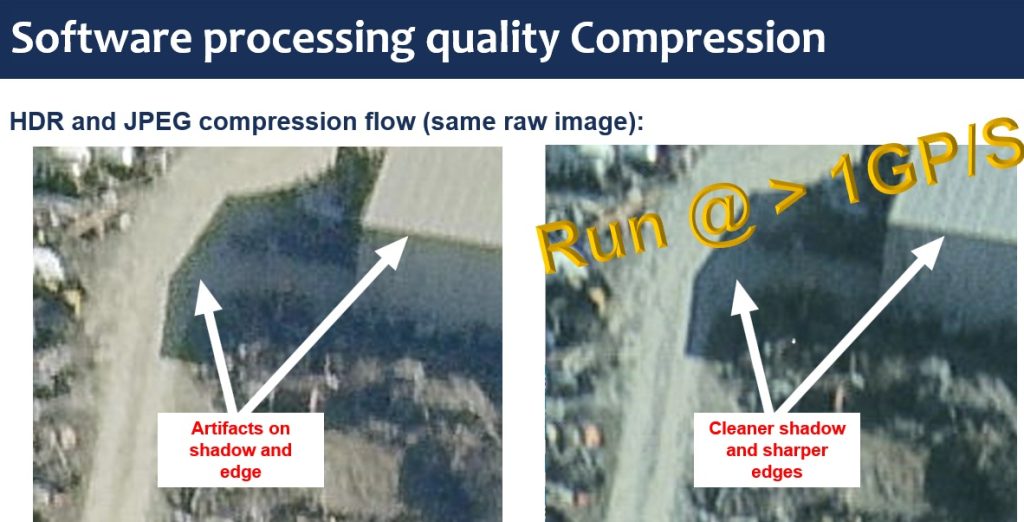
Compression
Another sometimes-useful technique is compression, reducing transmission volume (and time). Ideally one seeks lossless or low-loss compression, but that’s a tradeoff typically determined by assessing performance outcomes against any rigor or risk requirements for outlying cases. Often “good enough” and demonstrably reliable is the preferred choice.
If your application is NOT challenged by data transfer volume and time… whilst sending uncompressed images, then you don’t need compression. Conversely, might compression speed up your application for a competitive advantage?
Or thinking outside the box, might there be innovative applications doable with compression that aren’t possible without it? Let us help you do the math. Or try some applied testing.
Gamma correction and white balance
Yet another digital imaging tool is gamma correction, an operation on luminance values. It was originally introduced to adapt digital images and map them better to human visual perception, due to the ways our eyes perceive brightness. BUT it also helps machine vision algorithms perform better by linearizing color and brightness data. That can improve accuracy in object tracking and color segmentation, for example.
Likewise for white balance. Here too the origin of white balance was to create a more pleasing image for human viewers of digitally rendered images, so that “white” objects appear white even if the light source skewed a bit blue or yellow, for example.
It turns out that white balance is also important for machine vision. By white balancing to the light source (if sunlight, it changes throughout the day), whether natural or artificial, color segmentation and mapping is improved. Whether doing inspection, object identification, or medical imaging, accurate color mapping is essential.
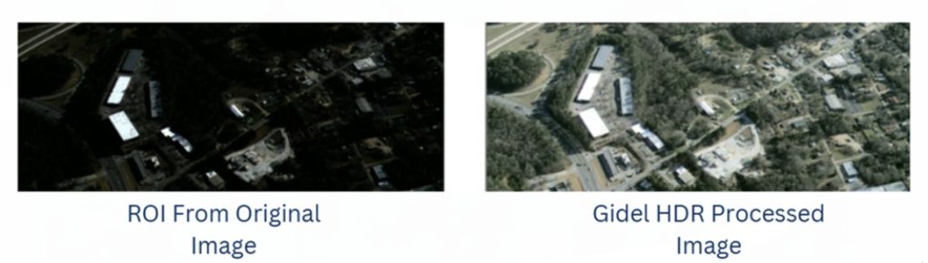
With HDR, Compression, white balance and Gamma correction
Throwing the whole kitchen sink at it, consider the following image pairs:
Do it in real-time, on board the frame grabber from Gidel
The above illustrations are pretty compelling. But imagine if that had to happen on your host PC, operating on large raw data images, while trying to keep up with incoming data from the camera that might overwhelm the PC’s ability to achieve the desired machine vision decisions. That’s where Gidel’s FPGA frame grabbers excel. They receive the raw image stream from the camera, and do real-time value-added pre-processing – very fast – before passing the improved (and optionally compressed) image to the host software. So the workload on the host is reduced.
Better images – faster
With many engineering design challenges, it can be difficult or impossible to simultaneously satisfy “qualitatively better” as well as “faster performance” criteria. Indeed some conceptualizable applications may not be doable in practice due to such constraints. Or may not be affordable with common interfaces.
With Gidel’s FPGA frame grabbers, you get improved speed and high-quality actionable images – for high-performance applications that deliver.

1st Vision’s sales engineers have over 100 years of combined experience to assist in your camera and components selection. With a large portfolio of cameras, lenses, cables, NIC cards and industrial computers, we can provide a full vision solution!
About you: We want to hear from you! We’ve built our brand on our know-how and like to educate the marketplace on imaging technology topics… What would you like to hear about?… Drop a line to info@1stvision.com with what topics you’d like to know more about.