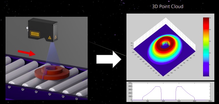
Test your parts in 3D lab

Have you wondered if 3D laser profiling would work for your application? Unless you have experience in 3D imaging, for which laser profiling is one of several popular methods, you may be uncertain of the fit for your application. Yes, one can read a comprehensive Tech Briefs on 3D methods, or product specifications, but wouldn’t it be helpful to see some images of your parts taken with an actual 3D Laser Profiler?
Image courtesy Teledyne DALSA.

While prototyping at your facility is of course one option, if your target objects can be shipped, Teledyne DALSA has a Z-Trak Application Lab, whose services we may be able to arrange at no cost to you. Just describe your application requirements to us, and if 3D laser profiling sounds promising, the service works as follows:

  1. Send in representative samples (e.g. good part, bad part)
  2. We’ll configure Z-Trak Application Lab relative to sample size, shape, and applications goals, and run the samples to obtain images and data
  3. We’ll send you data, images, and reports
  4. Together we’ll interpret the results and you can decide if laser profiling is something you want to pursue

Really, just send samples in? Anything goes? Well not anything. It can’t be 50 meters long. Maybe a 15 centimeter subset would be good enough for proof of concept? And if the sample is a foodstuff, it can’t suffer overnight spoilage before it arrives.
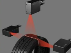
A phone conversation that discusses the objects to be inspected, their dimensions, and the applications goal(s) is all we need to qualify accepting your samples for a test. Image courtesy of Teledyne DALSA.


Case study

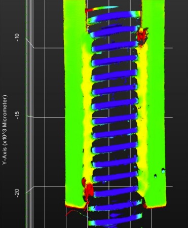
In this segment, we feature outtakes from a recent use of the Z-Trak Application Lab, for a customer who needs to do weld seam inspections. The objective is to image a metal part with two weld seams using a Z-Trak 3D Laser Profiler and produce 3D images for evaluation of application feasibility. The images and texts shown here are taken from an actual report prepared for a prospective customer, to give you an understanding of the service.
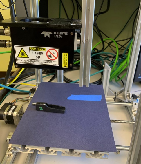
Equipment:

  • Z-Trak LP1-1040-B2
  • Movable X,Y stage
    X-Resolution: ~25 um
    Y-Resolution: 40 um
    WD: ~50 mm

Image courtesy Teledyne DALSA

Conditions:
The metal part was laid flat on the X,Y stage under the Z-Trak. The stage was moved
to scan the part.

To the right, see the image generated from a perpendicular scan of the metal part. Image courtesy Teledyne DALSA.
The composite image below requires some explanation. The graphs on the middle column, from top to bottom, show Left-Weld-Length, Right-Weld-Length, and Weld-Midpoint-Width (between the left and right welds), respectively. The green markup arrows help you correlate the measurements to the image on the left. The rightmost column includes summary measurements such as Min, Max, and Mean values.
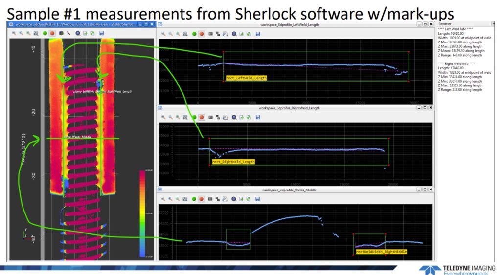
Image courtesy Teledyne DALSA

Now have a look at a similar screenshot, for Sample #2, which includes a “bad weld”:
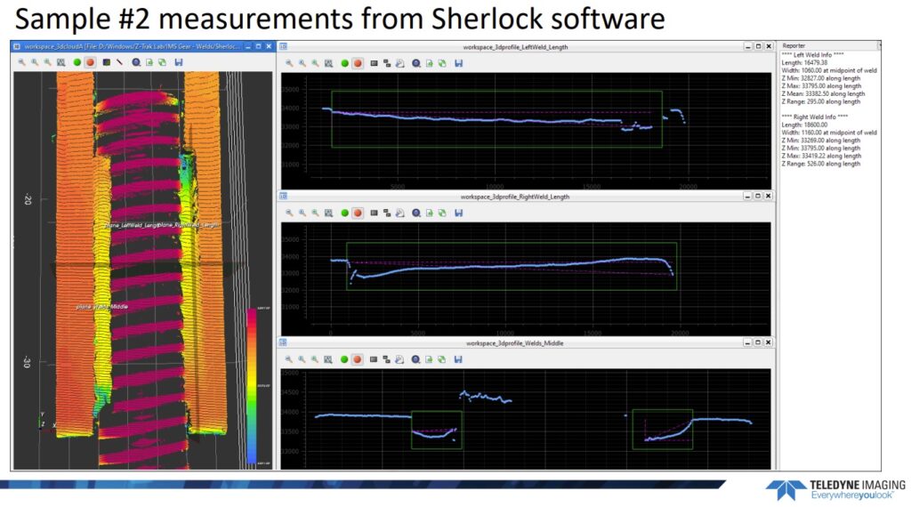
Image courtesy Teledyne DALSA

With reference to the image above, the customer report included the following passage:

The top-right image is the left weld seam profile. In the Reporter window the measurement of this seam is 1694.79 mm long. However, a defect can be noted at the bottom of the left weld. In addition to the defect it can be seen from the profile that the weld is not straight in the Z-direction. The weld is closer to the surface at the top and further from the surface at the bottom

Translation: The automated inspection reveals the defective weld! Naturally one would have to dig in further regarding definitions of “good weld”, “bad weld”, tolerances, where to set thresholds to balance yields and quality standards vs. too many false positives, etc.

Conclusion

The report provided to the customer concluded that “This application is feasible using a Z-Trak 3D Laser Profiler.” While it’s likely that outcome will be achieved if we qualify your samples and application to use the Z-Trak Application Lab service, it’s not a foregone conclusion. We at 1stVision and our partner Teledyne DALSA are in the business of helping customers succeed, so we’re not going to raise false hopes of application success.

Recap

To summarize, the segments above are representative outtakes from an actual report prepared by the Z-Trak Application Lab. The full report contains more images, data, and analysis. Our goal here is to give you a taste for the complimentary service, to help you consider whether it might be helpful for your own application planning process.

Next steps?

To learn more, see a recent blog “Which Z-Trak 3D camera is best for my application?“. Or have a look at the Z-Trak product overview.

If you’d like to send in your parts, please use this “Contact Us” link or the one below. In the ‘Tell us about your project’ field, just write something like “I’d like to have parts sent to the Z-trak lab.” If you want to write additional details, that’s cool – but not required. We’ll call to discuss details at your convenience.

1st Vision’s sales engineers have over 100 years of combined experience to assist in your camera and components selection.  With a large portfolio of lensescablesNIC card and industrial computers, we can provide a full vision solution!
Ensenso – 1stVision expands 3D portfolio with stereo vision

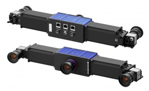
IDS Ensenso 3D cameras
Ensenso 3D Cameras – Courtesy of IDS

Most industries go through waves of technology and product innovation as they mature. In powered flight we had propellers long before jets, though each still has its place. In machine vision, 1D and 2D imaging took several decades to mature before 3D moved from experimentation and early innovation to mature products affordable to many. Download our Tech BriefWhich 3D imaging technique is best for my application?“, if you haven’t yet committed to a particular approach.

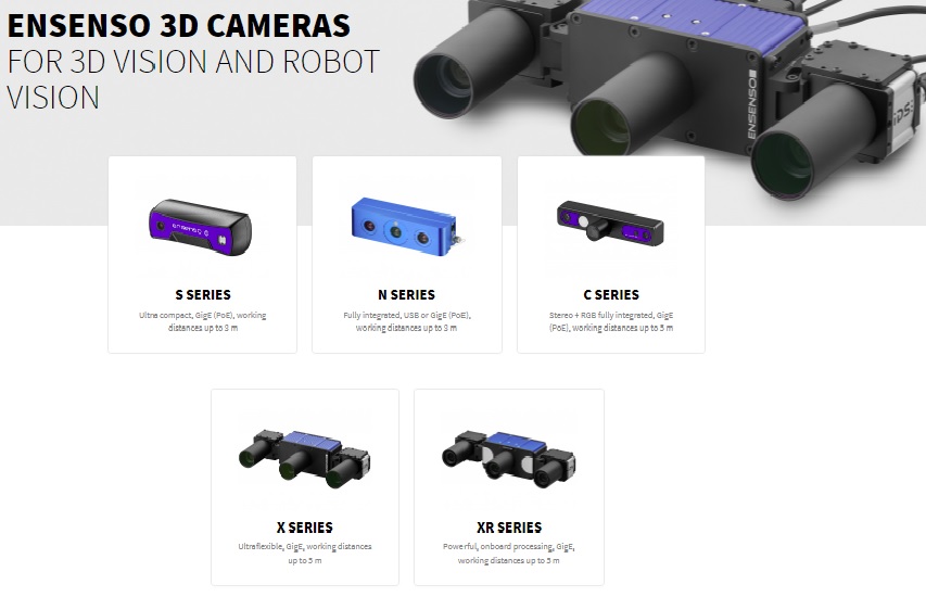
Stereo vision is one of the fastest growing approaches to 3D imaging, thanks to Moore’s Law and ever more powerful and compact cameras, processing power, together with modularized and turnkey products. 1st Vision is pleased to represent IDS Imaging’s Ensenso series of 3D cameras. In addition to the downloadable Tech Brief linked above, we encourage you to read on for an overview of all four Ensenso 3D camera families, the S, N, C, and X Series, respectively. If you prefer we guide you directly to a best-fit for your application, just give us a call at 978-474-0044.


Before we get to several different stereo vision series, and their respective capabilities, we note that IDS’ Ensenso S Series in fact utilizes the structured light approach rather than stereo vision. Per the Tech Brief linked above, there are several ways to do 3D.

S Series

Ensenso S Series are compact 3D industrial cameras combining AI software with 3D infrared laser point triangulation, generating point clouds to Z dimension accuracy of 2.4 mm at 1 meter distance. They are a cost-effective solution for many budget-conscious and high volume 3D applications. Each is in a zinc housing with IP65/67 protection.

3D imaging via structured light – Courtesy of IDS

Back to stereo vision, IDS Ensenso  N, C, X and XR 3D Series are based on the stereo vision principle.

The Stereo Vision principle – Courtesy of IDS

N Series

Ensenso N Series 3D cameras are designed for harsh industrial environments and pre-calibrated for easy setup.  N Series 3D cameras are “TM Plug & Play” certified by Techman Robot, and suitable for many 3D applications such as robotics and factory automation.

The Ensenso N Series 3D camera works for either static or moving objects even in changing or low light conditions.  With IP65/67 protection, and a compact design, the Ensenso N Series 3D cameras fit into tight spaces or in moving components such as robotic arms. There are two variants:

  • N3X: aluminum housing for optimal heat dissipation in extreme environments
  • N4X: cost-effective plastic composite housing

C Series

The Ensenso C Series 3D camera, also uses stereo vision, but additionally embeds a color CMOS RGB sensor, pre-calibrated and aligned with the stereo vision system. This allows a “colorized” effect as shown in the video clip below, where one sees 3 adjacent image pairs. Each “right image” is the colorized augmentation on top of the initial stereo point cloud view to its left. Most would agree it lends a more realistic look.

Color sensor lends more realistic look to point cloud – Courtesy IDS

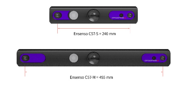
The C Series delivers Z accuracy 0.1 mm at 1 meter distance, with the C-57S, or 0.2mm at 2 meters, with C-57M.

Ensenso C Series – small or medium option – Courtesy of IDS

X Series

Ensenso X Series 3D camera is an ultra-flexible, modular, 3D GigE industrial camera system. The X Series 3D camera systems are available with a choice of two variants: X30 and X36.

Ensenso X Series – Courtesy IDS

The Ensenso X30 3D camera system is designed to capture moving objects making it suitable for many industrial applications such as factory automation production lines, and bin picking.

For static objects, use the Ensenso X36 3D camera system. FlexView2 greatly increases the resolution producing 3D images with precise detail and definition of the objects being captured even with low light or reflective surfaces.

The Ensenso X 3D camera system includes a 100 watt LED projector with an integrated GigE power switch. The 3D camera system can be configured with many GigE uEye cameras and a 1.6 or 5 megapixel CMOS monochrome sensor to create your customized 3D imaging system.

Working distances may be up to 5m, and point cloud models may be developed for objects up to 8 cubic meters in volume!


All of the above cameras include the Ensenso SDK software that accelerates the application set up, configuration and development time. Ensenso 3D cameras are ideal for numerous industrial 3D applications including robotics, logistics, factory automation, sorting, and quality assurance.

1st Vision’s sales engineers have over 100 years of combined experience to assist in your camera and components selection.  With a large portfolio of lensescablesNIC card and industrial computers, we can provide a full vision solution!

37M and 67M 10GigE cameras | Higher resolution and speed!

Teledyne DALSA 10GigE Genie Nano

In this focused blog we call out 4 specific camera models with 10GigE interfaces, ideal for life sciences and security applications, though of course not limited to those. In particular, there are two 1:1 square format sensors, with 37 and 67M pixels, respectively, that each come in monochrome and color offerings.

Teledyne DALSA 10GigE Genie Nano
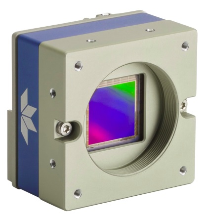
Genie Nano 10GigE camera : courtesy Teledyne DALSA

Context if you want it: Teledyne DALSA recently augmented its Genie Nano series, to include the 10GigE interface, beyond the previous 1, 2, and 5GigE offerings, per our overview blog released in June 2023. Of particular interest there is a graphic showing throughput by interface across the whole range of Teledyne area scan cameras. It’s a convenient way of understanding how the different levels of GigE interface compare to USB, CameraLink, and CXP interfaces.


Back to the 37 and 67M cameras in particular… What makes these cameras distinctive in the current market?

Non-stitched sensors:

These sensors are non-stitched. While some competitors use dual or quad sensor readout zones to drive framerates, they have to work hard to achieve tap balance outcomes satisfactory to the user – not easy under certain conditions. But with the 10GigE interface, when image quality is paramount for your application, these cameras deliver impressive framerates and images free from any tap balance artefacts. At full resolution, the 67M camera delivers 15fps, and the 37M provides 20fps.

If you love these two sensors, and want even faster framerates than what 10GigE can support, note that the same sensors appear in the Falcon4 with the CameraLink High Speed (CLHS) interface. With CLHS these sensors deliver 90 and 120fps, respectively!

Other features of note:

  • 67M model is the most compact on the market at 41 mm x 59 mm x 59 mm
  • Multi-ROI up to 16 regions – further boost framerates by moving only essential image data
  • Robust and performant Teledyne Sapera driver or 3rd party GenICam compliant SDKs
  • 10 – 36V or PoE (single cable for power, data, and control signals)
  • M42 lens mount

Precision Time Protocol (PTP) synchronization of two or more cameras over GigE network, avoiding the need for hardware triggers and controllers, for many applications.

Uniquely from Teledyne DALSA is their proprietary Trigger to Image Reliability (T2IR):

  • Manage exceptions in a controlled manner
  • Verify critical imaging events such as lost frames, lines, or triggers
  • Tag images for traceability
Trigger to Image Reliability (T2IR) – courtesy Teledyne DALSA

The Teledyne e2V sensors used in these cameras are designed and produced here in North America. Not to play politics when we all participate in global supply chains in our personal and professional lives, but for certain contract approvals or risk assessments it can be beneficial when the country of origin question is any easy one to answer.

Sometimes new camera families or models are just “me too” market followers – often worthy but not innovative as such. But the Genie Nano 10G-M/C-6200 and 10G-M/C–8200 cameras are game changers. Call us for a quote! 978-474-0044.

Even if you don’t need the resolution or performance of the 37 or 67M Genie Nano 10GigE right now, the Teledyne DALSA Genie Nano families include products using 1, 2, and 5GigE, 10GigE, CXP, and CLHS interfaces. That ranges from “fast enough” (and modestly priced) through fast and on to very fast. If you have diverse imaging projects, there are economies of scale, and efficiencies in deployment, by using drivers, SDKs, and features shared by multiple cameras – and mastered by your team.

1st Vision’s sales engineers have over 100 years of combined experience to assist in your camera and components selection.  With a large portfolio of lensescablesNIC card and industrial computers, we can provide a full vision solution!
3D Scanning Applications with AT Automation Technology

Previously we’ve introduced AT Automation Technology 3D scanners, which use triangulation – together with precision optics and embedded algorithms – to build a point cloud representation of 3D objects.

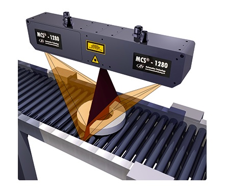
AT Automation Technology 3D scanner
– courtesy of Automation Technology

While there are interesting scanning applications in diverse industries, including automotive, food processing, battery production, display inspection, and more, in this piece we focus on the automotive industry. Below we offer a collection of short videos that help to tell the story. Each application utilizes AT Automation Technology 3D laser profilers.

CONTACT US to discuss your application! We have longstanding returning customers who know we like to help you choose the right cameras and components. It’s what we do.

Inspection of brake discs, for surface defects, duration 1 minute 24 seconds:


Inspection of stamped metal parts, duration 37 seconds:


Inspecting asymmetrical objects, duration 50 seconds:


You don’t have to be in the automotive industry to take advantage of AT Automation Technology 3D laser scanning! Food processing, display inspection, battery production – indeed all sorts of 3D applications are enabled or enhanced by laser triangulation approaches to building 3D point clouds for a scanned object, and comparing the scan to the idealized perfect object. The difference calculation determines if the test object is within the defined tolerances.

3D point cloud
From real space to 3D point cloud model – Image courtesy of AT Automation Technology

We have videos for other industries and applications available, and sales engineers who can help guide you to a solution for your particular needs. Call us at 978-474-0044.

1st Vision’s sales engineers have over 100 years of combined experience to assist in your camera and components selection.  With a large portfolio of lensescablesNIC card and industrial computers, we can provide a full vision solution!