Learn how an Allied Vision Mako camera can control your LED light source

camera as controller

In this article we discuss when and why one might want to strobe a light instead of using continuous lighting. While strobing traditionally required a dedicated controller, we go on to introduce that CCS and AVT have published an Application Note showing how the Allied Vision Mako camera can serve as the controller!

While LED lights are often used for continuous lighting, since that’s an easy mode of deployment, sometimes an application is best served with a well-timed strobe effect. This might be for one or more of the following reasons:

  • to “freeze motion” via light timing rather than shutter control alone;
  • to avoid the heat buildup from continuously-on lights
  • overwhelm ambient lighting
  • maximize lamp lifetime
Effilux LED lights

Let’s suppose you’ve already decided that you require strobe lighting in your application. You’re past “whether” and on to “how to”.

Since you are moving into the realm tight timing tolerances, it’s clear that the following are going to need to be coordinated and controlled:

  • the strobe light start and stop timing, possibly including any ramp-up delays to full intensity
  • the camera shutter or exposure timing, including any signal delays to start and stop
  • possibly the physical position of real world objects or actuators or sensors detecting these

Traditionally, one used and external controller, an additional device, to control both the camera and the lighting. It’s a dedicated device that can be programmed to manage the logical control signals and the appropriate power, in the sequence required. This remains a common approach today – buy the right controller and configure it all, tuning parameters through calculations and empirical testing.

Effilux pulse controller: controls up to 4 lights; output current can reach up to 1A @ 30V in continuous and 10A @ 200V in strobe mode – courtesy Effilux

Call us if you want help designing your application and choosing a controller matched to your camera and lighting requirements.

But wait! Sometimes, thanks to feature-rich lighting equipment and cameras, with the right set of input/output (I/O) connections, and corresponding firmware-supported functionality, one can achieve the necessary control – without a separate controller. That’s attractive if it can reduce the number of components one needs to purchase. Even better, it can reduce the number of manuals one has to read, the number of cables to connect, and the overall complexity of the application.

Let’s look at examples of “controller free” applications, or more accurately, cameras and lights that can effect the necessary controls – without a separate device.

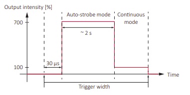
Consider the following timing diagram, which shows the behavior of the Effi-Ring when used in auto-strobe mode. That doesn’t mean it strobes randomly at times of its own choosing! Rather it means that when triggered, it strobes at 300% of continuous intensity until the trigger pulse falls low again, OR 2 seconds elapse, whichever comes first. Then if steps down to continuous mode at 100% intensity. This “2 seconds max” feature, far longer than most strobed applications require, is a design feature to prevent overheating.

Courtesy Allied Vision Technologies

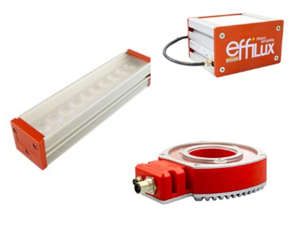
OK, cool. So where to obtain that nice square wave trigger pulse? Well, one could use a controller as discussed above. But in the illustration below, where’s the controller?!? All we see are the host computer, an Allied Vision Mako GigE Vision camera, an Effilux LED, a power supply, and some cabling.

Camera exposure signal controls strobe light – courtesy Allied Vision Technologies

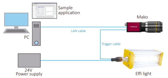
How is this achieved without a controller? In this example, the AVT Mako camera and the Effilux light are “smart enough” to create the necessary control. While neither device is “smart” in the sense of so-called smart cameras that eliminate the host computer for certain imaging tasks, the Mako is equipped with opto-isolated general purpose input output (GPIO) connections. These GPIOs are programmable along with many other camera features such as shutter (exposure), gain, binning, and so forth. By knowing the desired relationship between start of exposure, start of lighting, and end of exposure, and the status signals generated for such events, one can configure the camera to provide the trigger pulse to the light, so that both are in perfect synchronization.

Note: During application implementation, it can be helpful to use an oscilloscope to monitor and tune the timing and duration of the triggers and status signals.

Whether your particular application is best served with a controller, or with a camera that doubles as a controller, depends on the application and camera options available. 1stVision carries a wide range of Effilux LED lights in bar, ring, backlight, and dome configurations, together with the ability to be used on continuous or strobe modes.

1st Vision’s sales engineers have over 100 years of combined experience to assist in your camera and components selection.  With a large portfolio of lensescablesNIC card and industrial computers, we can provide a full vision solution!

What can you do with 3D from Automation Technology?

Automation Technology GmbH C6 Laser Sensor

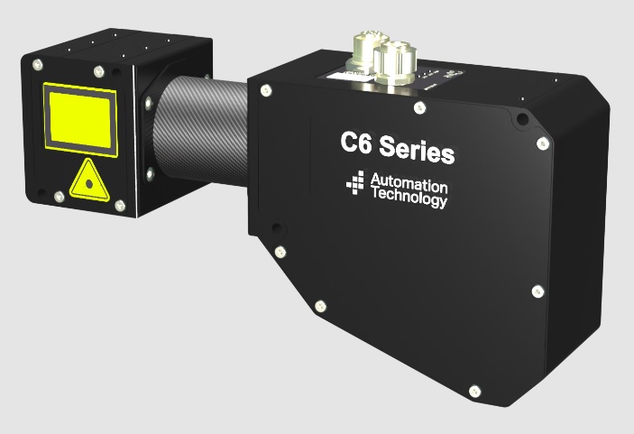
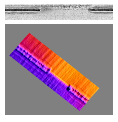
When new technologies or product offerings are introduced, it can help get the creative juices flowing by seeing example applications. In this case, 3D laser triangulation isn’t new, and Automation Technology (AT) has more than 20 years’ experience developing and supporting their products. But 1stVision has now been appointed by AT as their North American distributor – a strategic partnership for both organizations bring new opportunities to joint customers.

Laser Triangulation overview – courtesy Automation Technology

The short video above provides a nice overview of how laser triangulation provides the basis for 3D imaging in Automation Technology GmbH’s C6 series of 3D imagers.

With no ranking implied by the order, we highlight applications of 3D imaging using Automation Technology products in each of:


Weld inspection

Weld inspection is essential for quality control, whether pro-actively for customer assurance and materials optimization or to archive against potential litigation.

Weld inspection – courtesy of Automation Technology
  • 3D Inspections provide robust, reliable, reproducible measured data largely independent of ambient light effects, reflection and the exact positioning of the part to be tested
  • High resolution, continuous inspection of height, width and volume
  • Control of shape and position of weld seams
  • Surface / substrate shine has no influence on the measurement

Optionally combine with an IR inspection system for identification of surface imperfections and geometric defects.


Rail tracks and train wheels

Drive-by 3D maintenance inspection of train wheel components and track condition:

  • Detect missing, loose, or deformed items
  • Precision to 1mm
  • Speeds up to 250km/hr
Train components and rail images – courtesy Automation Technology

Rolling 3D scan of railway tracks:

  • Measure rail condition relative to norms
  • Log image data to GPS position for maintenance scheduling and safety compliance
  • Precision to 1mm
  • Speeds up to 120km/hr

Additional rail industry applications: Tunnel wall inspection; catenary wire inspection.


Adhesive glue beads

Similar in many ways to the weld inspection segment above, automated glue bead application also seeks to document quality standards are met, optimize materials usage, and maximize effective application rates.

Glue bead – courtesy of Automation Technology

Noteworthy characteristics of 3D inspection and control of glue bead application include:

  • Control shape and position of adhesive bead on the supporting surface
  • Inspect height, width and volume
  • Control both inner and outer contour
  • Application continuity check
  • Volumetric control of dispensing system
  • Delivers robust, reliable, reproducible measured data largely independent of ambient light effects, reflection and exact positioning of the items being tested

Automation Technology C6 3D sensor

1st Vision’s sales engineers have over 100 years of combined experience to assist in your camera and components selection.  With a large portfolio of lensescablesNIC card and industrial computers, we can provide a full vision solution!

New IDS XLS cameras – tiny cameras – low-price category

IDS XLS board level cameras

The smallest board-level cameras in the IDS portfolio, the uEye XLS cameras have very low power consumption and heat generation. They are ideal for embedded applications and device engineering. Sensors are available for monochrome, color, and NIR.

XLS board-level with no lens mount; with S-mount; with C-mount – courtesy of IDS

The “S” in the name means “small”, as the series is a compact version of the uEye XLE series. As small as 29 x 29 x 7 mm in size! Each USB3 camera in the series is Vision Standard compliant, has a Micro-B connector, and offers a choice of either C/CS lens mount, S-mount, or no-mount DIY.

IDS uEye XLS camera familycourtesy of IDS

Positioned in the low-price portfolio, the XLS cameras are most likely to be adopted by customers requiring high volumes for which basic – but still impressive – functions are sufficient. The XLS launch family of sensors include ON Semi AR0234, ON Semi AR0521, ON Semi AR0522, Sony IMX415, and Sony IMX412. These span a wide range of resolutions, framerates, and frequency responses. Each sensor appears in 3 board-level variants per the last digit in each part number corresponding as follows: 1 = S-mount, 2 = no-mount, 4 = C, CS-mount.

SensorResolutionFramerateMonochromeColorNIR
ON Semi AR02341920
x
1200
102 fpsU3-356(1/2/4)
XLS-M
U3-356(1/2/4)
XLS-C
ON Semi AR05212592
x
1944
48 fpsU3-
368(1/2/4)
XLS-M
U3-
368(1/2/4)
XLS-C
ON Semi AR05222592
x
1944
48 fpsU3-368(1/2/4)
XLS-NIR
Sony
IMX415
3864
x
2176
25 fpsU3-38J(1/2/4)
XLS-M
U3-38J(1/2/4)
XLS-C
Sony
IMX412
4056
x
3040
18 fpsU3-38L(1/2/4)
XLS-C
XLS family spans 5 sensors covering a range of requirements
XLS dimensions, mounts, and connections – courtesy of IDS

Uses are wide-ranging, skewing towards high-volume embedded applications:

Example applications for XLS board-level cameras – courtesy of IDS

In a nutshell, these are cost-effective cameras with basic functions. The uEye XLS cameras are small, easy to integrate with IDS or industry-standard software, cost-optimized and equipped with the fundamental functions for high-quality image evaluation

1st Vision’s sales engineers have over 100 years of combined experience to assist in your camera and components selection.  With a large portfolio of lensescablesNIC card and industrial computers, we can provide a full vision solution!

How to select an industrial or machine vision camera?

How to select a camera

Why should I read about how to select an industrial camera, when I could just call 1stVision as a distributor of cameras, lenses, lighting, software, and cables, and let you recommend a solution for me?

Well yes, you could – and ultimately we believe a number of you who read this will in fact call us, as have many before. But when you take your car to the mechanic, do you just tell him “sometimes it makes a funny noise”? Or do you qualify the funny noise observation by noting at what speed it happens? When driving straight or turning in one direction? Whether it correlates to the ambient temperature or whether the vehicle is warmed up – or not?

How to select a camera

The best outcomes tend to come from partnerships where both the customer and the provider each bring their knowledge to the table – and work together to characterize the problem, the opportunity, and the solution. In our many years of expertise helping new and returning customers create machine vision solutions, the customers with the best outcomes also make the effort to dig in and understand enough about cameras and other components in order to help us help them.

So how does one in fact choose an industrial or machine vision camera?

An industrial camera is a camera, often embedded in or connected to a system, used for commercial or scientific applications. Additionally, machine systems are often fully automated, or at least partially automated, with long duty cycles. Applications are many, ranging from surveillance, process control, quality control, pick and place, biomedical, manufacturing, and more.

Further, the camera may be moving – or stationary, or the target might be moving – or stationary. And the wavelengths of light best-suited to achieving intended outcomes may be in the visible spectrum – the same spectrum we see – or the application may take advantage of ultraviolet (UV) or infrared (IR) characteristics.

So where to begin? First we need to characterize the application to be developed. Presumably you know or believe there’s an opportunity to add value by using machine vision to automate some process by applying computer controlled imaging to improve quality, reduce cost, innovate a product or service, reduce risk, or otherwise do something useful.

Now let’s dig into each significant consideration, including resolution, sensor selection frame rate, interface, cabling, lighting, lens selection, software, etc. Within each section we have links to more technical details to help you focus on your particular application.

Resolution: This is about the level of detail one needs in the image, in order to achieve success. If one just needs to detect presence or absence, a low resolution image may be sufficient. But if one needs to measure precisely, or detect fine tolerances, one needs a far more pixels that correlate to the fine-grained features from the real-world details being imaged.

The same real-world test chart imaged with better resolution on the left than on the right, due to one or both of sensor characteristics and/or lens quality

A key guideline is that each minimal real-world feature to be detected should appear in a 3×3 pixel grid in the image.  So if the real-world scene is X by Y meters, and the smallest feature to be detected is A by B centimeters, assuming the lens is matched to the sensor and the scene, it’s just a math problem to determine the number of pixels required on the sensor. Read more about resolution requirements and calculations.

Sensor selection: So the required resolution is an important determinant for sensor selection. But so is sensitivity, including concepts like quantum efficiency. Pixel size matters too, as an influencer on sensitivity, as well as determining sensor size overall. Keys to choosing the best image sensor are covered here.

image sensor

Wavelength: Sensor selection is also influenced based on the wavelengths being using in the application.     Let’s assume you’ve identified the wavelength(s) for the application, which determines whether you’ll need:

  • a CMOS sensor for visible light in the 400 – 700nm range
  • a UV sensor for wavelengths below 400nm
  • a Near Infrared sensor for 750 – 900nm
  • or SWIR and XSWIR to even longer wavelengths up to 2.2µm

Monochrome or color? If your application is in the visible portion of the spectrum, many first-timers to machine vision assume color is better, since it would seem to have more “information”. Sometimes that intuition is correct – when color is the distinguishing feature. But if measurement is the goal, monochrome can be more efficient and cost-effective. Read more about the monochrome vs. color sensor considerations.

Area scan vs. line scan? Area scan cameras are generally considered to be the all-purpose imaging solution as they use a straight-forward matrix of pixels to capture an image of an object, event, or scene. In comparison to line scan cameras, they offer easier setup and alignment. For stationary or slow moving objects, suitable lighting together with a moderate shutter speed can produce excellent images.

In contrast to an area scan camera, in a line scan camera a single row of pixels is used to capture data very quickly. As the object moves past the camera, the complete image is pieced together in the software line-by-line and pixel-by-pixel. Line scan camera systems are the recognized standard for high-speed processing of fast-moving “continuous” objects such as in web inspection of paper, plastic film, and related applications. An overview of area scan vs. line scan.

Frame-rate: If your object is stationary, such as a microscope slide, frame rate may be of little importance to you, as long as the entire image can be transferred from the camera to the computer before the next image needs to be acquired. But if the camera is moving (drive-by-mapping, or camera-on-robot-arm) or the target is moving (fast moving conveyor belt or a surveillance application), one must capture each image fast enough to avoid pixel blur – and transfer the images fast enough to keep up. How to calculate exposure time?

Interfaces: By what interface should the camera and computer communicate? USB, GigE, Camera Link, or CoaXPress? Each has merits but vary by throughput capacity, cable lengths permitted, and cost. It’s a given that the interface has to be fast enough to keep up with the volume of image data coming from the camera, relative to the software’s capability to process the data. One must also consider whether it’s a single-camera application, or one in which two or more cameras will be integrated, and the corresponding interface considerations.

Cabling: So you’ve identified the interface. The camera and computer budget is set. Can you save a bit of cost by sourcing the cables at Amazon or eBay, compared to the robust ones offered by the camera distributor? Sometimes you can! Sometimes not so much.

Lighting: While not part of the camera per se, for that sensor you’re now liking in a particular camera model, can you get enough photons into the pixel well to achieve the necessary contrast to discern target from background? While sensor selection is paramount, lighting and lensing are just a half-step behind in terms of consideration with the most bearing on application outcomes. Whether steady LED light or strobed, bright field or dark field, visible or IR or UV, lighting matters. It’s worth understanding.

Filters: Twinned closely with the topic of lighting, well-chosen filters can “condition” the light to polarize it, block or pass certain frequencies, and can generally add significant value. Whether in monochrome, color, or non-visible portions of the spectrum, filters can pay for themselves many times over in improving application outcomes.

Lens selection: Depending on resolution requirements, sensors come in various sizes. While always rectangular in shape, they have differing pixel densities, and differing overall dimensions. One needs to choose a lens that “covers” the light-sensitive sections of the sensor, so be sure to understand lens optical format. Not only does the lens have to be the right size, one also has to pay attention to quality. There’s no need to over-engineer and put a premium lens into a low-resolution application, but you sure don’t want to put a mediocre lens into a demanding application. The Modulation Transfer Function, or MTF, is a good characterization of lens performance, and a great way to compare candidate lenses.

Software: In machine vision systems, it’s the software that interprets the image and takes action, whether that be accept/reject a part, actuate a servo motor, continue filling a bottle or vial, log a quality control image, etc. Most camera providers offer complementary software development kits (SDKs), for those who want to code camera control and image interpretation. Or there are vendor-neutral SDKs and machine vision libraries – these aren’t quite plug-and-play – yet – but they often just require limited parameterization to achieve powerful camera configuration and image processing.

Accessories: How about camera mounts? Wash-down enclosures for food-processing or dusty environments? If used outdoors, do you need heating or cooling, or condensation management? Consider all aspects for a full solution.

1st Vision’s sales engineers have over 100 years of combined experience to assist in your camera and components selection.  With a large portfolio of lensescablesNIC card and industrial computers, we can provide a full vision solution!