How to eliminate glare in machine vision systems

Machine vision – indeed human vision too – relies heavily on contrast. The feature(s) being identified need to stand out against any competing candidate features. Otherwise confusion is present. Which means vision either doesn’t work, or isn’t efficient.

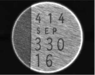
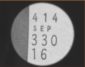
While it’s easy to achieve good contrast in certain machine vision applications, sometimes we’re presented with the special challenges of glare. The target object is the same, in the two images below. If the goal is to read the alphanumeric information, which image would you rather pass to your machine vision software?
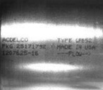
Courtesy:
Advanced Illumination
Courtesy: Advanced Illumination

Techniques to eliminate glare

Glare can arise due to highly reflective surfaces, especially in combination with the direction of the light source relative to the lens and sensor capturing the image. Thankfully there are a number of techniques to eliminate or substantially reduce glare.

Off-axis lighting

For the 1-D bar code reading application illustrated below, moving the light to an off-axis position creates dark field orientation, eliminating the glare. Identical materials but different geometry does the trick!
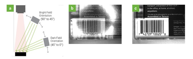
a. Lighting diagram; b. High-angle light reflects from specular surface; c. Off-axis light improves the image; Courtesy Advanced Illumination

Diverse lights and geometries

Consider another example. In this case we have a titration tray, with multiple wells. Each well has a laser-etched 2-D code.
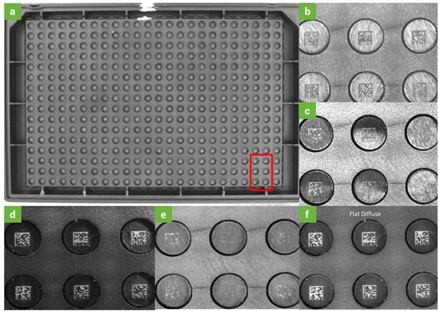
Analysis/discussion below. Courtesy Advanced Illumination
  • (a) the titration tray at low resolution, marked up with red outline around 6 wells isolated in high resolution images (b) – (f)
  • (b) High-angle ring light
  • (c) Coaxial light
  • (d) Dark field ring light
  • (e) Diffuse dome light
  • (f) Flat diffuse light

In this scenario, both (d) the dark field ring light, and (f) the flat diffuse light, are far superior to the other options, and the flat diffuse light is the winner.
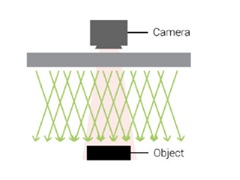
Flat diffuse light function diagram – light is directed downward, and more off-axis than a coaxial illuminator, yet less off-axis contribution than a dome light. Courtesy Advanced Illumination

NOTE: The example above is NOT meant to suggest that flat diffuse light is always the winner. It’s important to understand the characteristics of the surface you are inspecting, and each candidate type of lighting, and the geometric options. And to test!

Guideline

The following diagram is a general guideline, based upon the two most prevalent surface characteristics: (1) Surface flatness and texture, and (2) Surface reflectivity profile
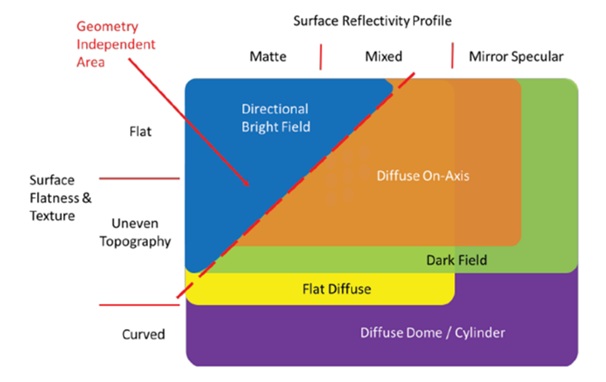
Guide to likely “best approach” based on prevalent surface characteristics – Courtesy Advanced Illumination

Send your samples

Lighting is a complex topic, so we’re happy to help. If you are uncertain which light type to choose and how to configure, we may be able to do some testing for you. Contact us to arrange sending samples to test in our lab, and we can recommend sensor, lensing, lighting, and configuration options.

For comprehensive coverage on glare reduction – and more – download A Practical Guide to Machine Vision lighting from our knowledge base.

1st Vision’s sales engineers have over 100 years of combined experience to assist in your camera and components selection.  With a large portfolio of cameraslensescablesNIC cards and industrial computers, we can provide a full vision solution!

About you: We want to hear from you!  We’ve built our brand on our know-how and like to educate the marketplace on imaging technology topics…  What would you like to hear about?… Drop a line to info@1stvision.com with what topics you’d like to know more about.

#glare

#contrast

#machinevisionlighting

#diffuser

#polariser

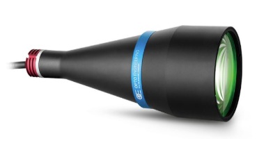
Collimated lighting important with telecentric lens

LTCLHP Collimated Light – Courtesy Opto Engineering

Machine vision practitioners, regardless of application or lens type, know that contrast is essential. Without sharp definition, features cannot be detected effectively.

When using a telecentric lens for precision optical 2-D measurements, ideally one should also use collimated lighting. Per the old adage about a chain being only as good as its weakest link, why invest in great lensing and then cut corners on lighting?

contact us

WITH collimated light expect high edge definition:

The cost of the light typically pays for itself relative to quality outcomes. Below see red-framed enlargements of the same region of a part being imaged by the same telecentric lens.

The left-hand image was taken with a conventional backlight – note how the light wraps around the edge, creating “confusion” and imprecision due to refracted light coming from all angles.

The right-hand image was obtained with a collimated backlight – with excellent edge definition.

Conventional backlight (left) vs. collimated backlight (right) – Courtesy Opto Engineering.

It all comes down to resolution

While telecentric imaging is a high-performance subset of the larger machine vision field in general, the same principles of resolution apply. It takes several pixels to confidently resolve any given feature – such as an edge – so any “gray areas” induced by lower quality lighting or optics would drag down system performance. See our blog and knowledge-base coverage of resolution for more details.

Collimated lighting in more detail

Above we see the results of using “diffuse” vs. “collimated” light sources, which are compelling. But what is a collimated light and how does it work so effectively?

UNLIKE a diffuse backlight, whose rays emanate towards the object at angles ranging from 0 to almost 180°, a collimated backlight sends rays with only very small deviations from perfectly parallel. Since parallel rays are also all that the telecentric lens receives and transmits on to the camera sensor, stray rays are mitigated and essentially eliminated.

The result is a high-contrast image which is easier to process with high-reliability. Furthermore, shutter speeds are typically faster, achieving necessary saturation more quickly, thereby shortening cycle times and increasing overall throughput.

Many lights to choose from:

The video below shows a range of light types and models, including clearly labeled direct, diffuse, and collimated lights.

Several light types – including clearly labeled collimated lights

[Optional] Telecentric concepts overview

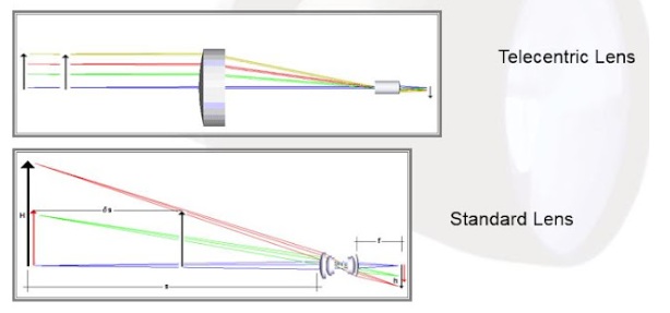
Below please compare the diagrams that show how light rays travel from the target position on the left, through the respective lenses, and on to the sensor position on the far right.

A telecentric lens is designed to insure that the chief rays remain parallel to the optical axis. The key benefit is that (when properly focused and aligned) the system is invariant to the distance of the object from the lens. This effectively ignores light rays coming from other angles of incidence, and thereby supports precise optical measurement systems – a branch of metrology.

If you’d like to go deeper on telecentrics, see the following two resources:

Telecentric concepts presented as a short blog.

Alternatively as a more comprehensive Powerpoint from our KnowledgeBase.

Video: Selecting a telecentric lens:

Call us at 978-474-0044 to tell us more about your application – and how we can guide you through telecentric lensing and lighting options.

1st Vision’s sales engineers have over 100 years of combined experience to assist in your camera and components selection.  With a large portfolio of cameraslensescablesNIC cards and industrial computers, we can provide a full vision solution!

About you: We want to hear from you!  We’ve built our brand on our know-how and like to educate the marketplace on imaging technology topics…  What would you like to hear about?… Drop a line to info@1stvision.com with what topics you’d like to know more about.

Conquer the glare: CCS LFXV Flat Dome Light for Machine Vision

While the endless parade of new CMOS sensors get plenty of attention, each bringing new efficiency or features, lighting and lensing are too often overlooked. The classic three-legged stool metaphor is an apt reminder that each of sensor, lighting, and lensing are critical to achieving optimal outcomes.

LFXV flat dome lights – courtesy CCS Inc.

Lighting matters

If you haven’t investigated the importance of lighting, or want a refresher, see our Knowledge Base resources on lighting. In those illustrated articles, we review the importance of contrast for machine vision, and how lighting is so critical. By choosing the best type of light, the optimal wavelength, and the right orientation, the difference in outcomes can be remarkable. In fact, sometimes with the right lighting design one can utilize less expensive sensors and lenses, achieving great results by letting the lighting do the work.

Pictures worth a thousand words

Before digging into product details on CCS LFXV flat dome lights, let’s take a look at examples achieved without… and with… the selected models.

Consider an example from electronics parts identification:

Hairline surface of capacitor makes text difficult to read, despite diffuse ring lite (red), a seemingly reasonable lighting choice – courtesy CCS Inc.
Using LFXV-25RD (red) flat dome light, hairline finish is essentially eliminated, creating much better contrast – courtesy CCS Inc.

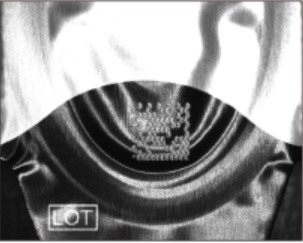
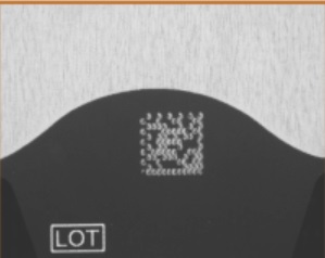
Here’s an example reading 2-D codes from contact lens packages:

Wavy and glossy surface makes 2-D code hard to discern with red ring light – courtesy CCS Inc.
LFXV50RD red flat dome light creates ideal contrast to read 2-D code – courtesy CCS Inc.

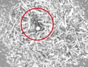
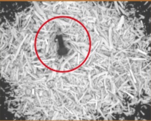
Consider identifying foreign materials in food products, for either automated removal or quality control logging:

Foreign object amidst tea leaves is barely discernable using white dome light – courtesy CCS Inc.
LFXV200IR infrared flat dome light creates contrast to easily identify the foreign object – courtesy CCS Inc.

More about wavelength

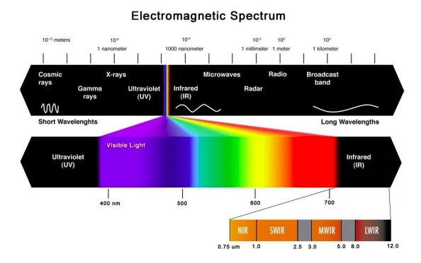
In the images above, you may have noticed various wavelengths were used – with better or worse outcomes. Above we showed “just” white light, red light, and infrared, but blue, green, and UV are also candidates, not to mention SWIR and LWIR. Light wavelength choice affects contrast – not just when using dome lights – see wavelengths overview in our knowledge base.

Key concepts

By way of contrast, let’s first look at the way a traditional dome light works:

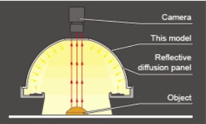
Traditional dome light design – courtesy CCS Inc.

Notice the camera is mounted to the top of a traditional dome light. The reflective diffusion panel coats all the inside surfaces of the dome – except where the camera is mounted. The diffusion pattern created is pretty good in general – but not perfect at hiding the camera hole entirely. If the target object is highly reflective and tends towards flat, one gets a dark spot in the center of the image…. and the application underperforms the surface inspection one hoped to achieve.

So who needs newfangled flat dome lights?

There’s nothing wrong with conventional dome lights per se, if you’ve got the space for them, and they do the job.

Three downsides to traditional dome lights

1. A traditional dome light may leave a dark spot – if the target is flat and highly reflective

2. A traditional dome light takes up a lot of space

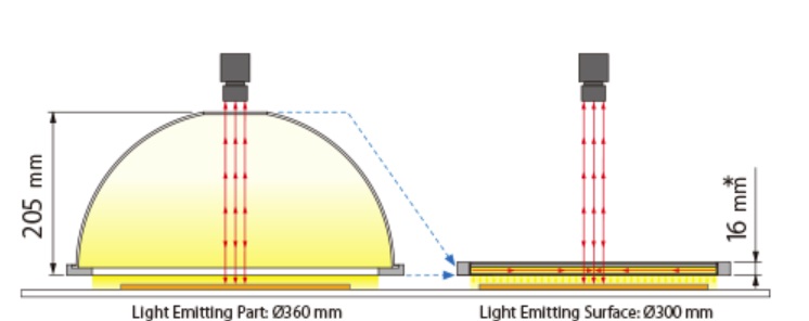
Conventional dome light on left vs. flat dome light on right – courtesy CCS Inc.

Notice how much space the conventional dome light takes up, compared to a “see through” LED flat dome light. But space-savings aren’t the only benefit to flat dome lights….

3. Working distance is “fixed” by a traditional dome light

Most imaging professionals know all about camera working distance (WD) and how to set up the optics for the camera sensor, a matching lens, and the object to be imaged, to get the optical geometry right.

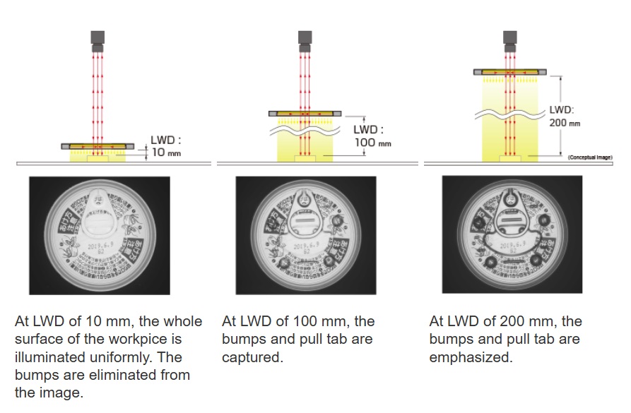
Now let’s take a look at light working distance (LWD). Consider the following can-top inspection scenarios:

By varying the light working distance (LWD), easily done with see-through flat LED dome lights, one can emphasize or de-emphasize features, according to application objectives – courtesy CCS Inc.

Wondering how to light your application?

Send us your sample(s)! If you can ship it, we can set up lighting in our labs to do the work for you.

1st Vision’s sales engineers have over 100 years of combined experience to assist in your camera and components selection.  With a large portfolio of cameraslensescablesNIC cards and industrial computers, we can provide a full vision solution!

About you: We want to hear from you!  We’ve built our brand on our know-how and like to educate the marketplace on imaging technology topics…  What would you like to hear about?… Drop a line to info@1stvision.com with what topics you’d like to know more about.

Monochrome light better for machine vision than white light

Black and white vs. color sensor? Monochrome or polychrome light frequencies? Visible or non-visible frequencies? Machine vision systems builders have a lot of choices – and options!

Let’s suppose you are working in the visible spectrum. You recall the rule of thumb to favor monochrome over color sensors when doing measurement applications – for same sized sensors.

So you’ve got a monochrome sensor that’s responsive in the range 380 – 700 nm. You put a suitable lens on your camera matched to the resolution requirements and figure “How easy, I can just use white light!”. You might have sufficient ambient light. Or you need supplemental LED lighting and choose white, since your target and sensor appear fine in white light – why overthink it? – you think.

Think again – monochrome may be better

Polychromatic (white) light is comprised of all the colors of the ROYGBIV visible spectrum – red, orange, yellow, green, blue, indigo, and violet – including all the hues within each of those segments of the visible spectrum. We humans perceive it as simple white light, but glass lenses and CMOS sensor pixels see things a bit differently.

Chromatic aberration is not your friend

Unless you are building prisms intended to separate white light into its constituent color groups, you’d prefer a lens that performs “perfectly” to focus light from the image onto the sensor, without introducing any loss or distortion.

Lens performance in all its aspects is a worthwhile topic in its own right, but for purposes of this short article, let’s discuss chromatic aberration. The key point is that when light passes through a lens, it refracts (bends) differently in correlation with the wavelength. For “coarse” applications it may not be noticeable; but trace amounts of arsenic in one’s coffee might go unnoticed too – inquiring minds want to understand when it starts to matter.

Take a look at the following two-part illustration and subsequent remarks.

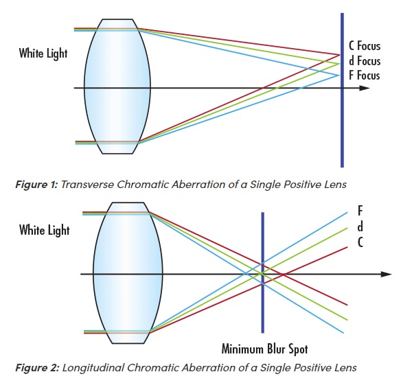
Transverse and longitudinal chromatic aberration – Courtesy Edmund Optics

In the illustrations above:

  • C denotes red light at 656 nm
  • d denotes yellow light at 587 nm
  • F denotes blue light at 486 nm

Figure 1, showing transverse chromatic aberration, shows us that differing refraction patterns by wavelength shift the focal point(s). If a given point on your imaged object reflect or emits light in two more more of the wavelengths, the focal point of one might land in a different sensor pixel than the other, creating blur and confusion on how to resolve the point. One wants the optical system to honor the real world geometry as closely as possible – we don’t want a scatter plot generated if a single point could be attained.

Figure 2 shows longitudinal chromatic aberration, which is another way of telling the same story. The minimum blur spot is the span between whatever outermost rays correspond to wavelengths occurring in a given imaging instance.

We could go deeper, beyond single lenses to compound lenses; dig into advanced optics and how lens designers try to mitigate for chromatic aberration (since some users indeed want or need polychromatic light). But that’s for another day. The point here is that chromatic aberration exists, and it’s best avoided if one can.

So what’s the solution?

The good news is that a very easy way to completely overcome chromatic aberration is to use a single monochromatic wavelength! If your target object reflects or emits a given wavelength, to which your sensor is responsive, the lens will refract the light from a given point very precisely, with no wavelength-induced shifts.

Making it real

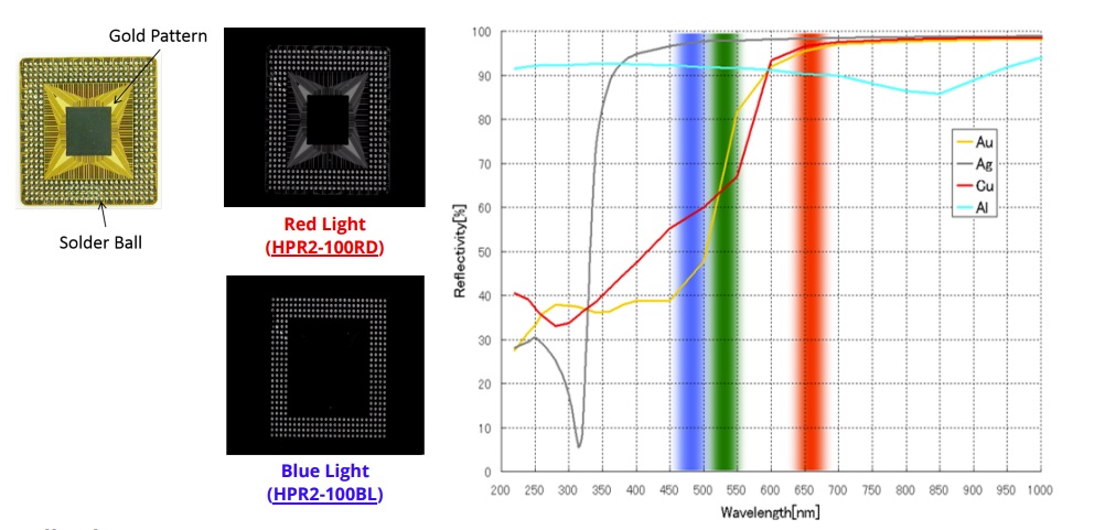
The illustration below shows that certain materials reflect certain wavelengths. Utilize such known properties to generate contrast essential for machine vision applications.

Red light reflects well from gold, copper, and silver – Courtesy CCS Inc.

In the illustration we see that blue light reflects well from silver (Ag) but not from copper (Cu) nor gold (Ag). Whereas red light reflects well from all three elements. The moral of the story is to use a wavelength that’s matched to what your application is looking for.

Takeaway – in a nutshell

Per the carpenter’s guidance to “measure twice – cut once”, approach each new application thoughtfully to optimize outcomes:

Click to contact
Give us an idea of your application and we will contact with lighting options and suggestions.

Additional resources you may find helpful from 1stVision’s knowledge base and blog articles: (in no particular order)

1st Vision’s sales engineers have over 100 years of combined experience to assist in your camera and components selection.  With a large portfolio of cameraslensescablesNIC cards and industrial computers, we can provide a full vision solution!

About you: We want to hear from you!  We’ve built our brand on our know-how and like to educate the marketplace on imaging technology topics…  What would you like to hear about?… Drop a line to info@1stvision.com with what topics you’d like to know more about.