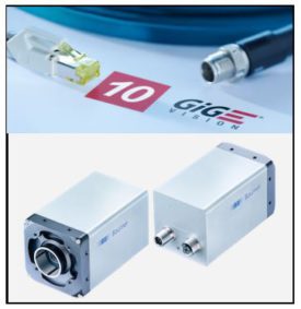
10 GigE Vision compliant cameras are easy to integrate enabling more machine vision applications and image processing. Camera image sensors have continued to increase in resolution which requires higher bandwidth interfaces to achieve high frame rates. 10 GigE cameras are a great solution as implementation is less costly and complex versus camera link and CoaxPress.
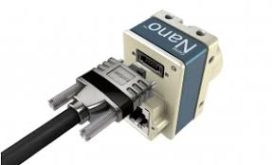
Aside from the features of 10GiGE Vision, the Baumer VLXT series cameras are extremely feature rich and cost competitive making them an excellent choice for 10GigE Vision cameras.
11 Key Features are listed below with many being unique, solving more vision applications in 10 GigE Vision cameras
1 – True 10GigE bandwidth! – 2 – Liquid lens & Canon EF mount control 3 – Exposure times down to 1uS with Sony Sensors 4 – Power outputs (4x) for direct driving LED lights eliminating a lighting controller. 5 – IP67 Ratings and extended temperatures for harsh environments 6 – IEEE 1588 Precision Timing protocols for synchronized timing with multiple devices. 7 – Long cable lengths up to 55 meters (Cat 6) and 70+ meters with Cat 6a / 7 and longer with optional fiber optic interface. 8 – Standard low cost 10GigE NIC’s can be used opposed to some manufacturers requiring special NICs 9 – Fully GigE Vision compliant for easy implementation with the benefits of high bandwidths. Allows support of third party software libraries. 10 – RS232 support 11 – On board JPEG compression available
1st Vision’s sales engineers have over 100 years of combined experience to assist in your camera selection. With a large portfolio of lenses, cables, NIC card and industrial computers, we can provide a full vision solution!
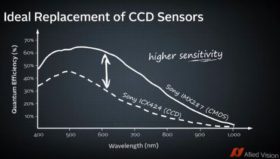
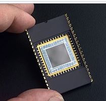
Industrial machine vision cameras historically have used CCD image sensors, but there is a transition in the industrial imaging marketplace to move to CMOS imagers. Why is this?.. Sony who is the primary supplier of image sensors announced in 2015 it will stop making CCD image sensors and is already past its last time buy. The market was nervous at first until we experienced the new CMOS image sensor designs. The latest Sony Pregius Image sensors provide increased performance with lower cost making it compelling to make changes to systems using older CCD image sensors.
What is the difference between CCD and CMOS image sensors in machine vision cameras?
Both produce an image by taking light energy (photons) and convert them into an electrical charge, but the process is done very differently.
In CCD image sensors, each pixel collects light, but then is moved across the circuit via current through vertical and horizontal shift registers. The light level is then sampled in the read out circuitry. Essentially its a bucket brigade to move the pixel information around which takes time and power.
In CMOS sensors, each pixel has the read out circuitry located at the photosensitive site. The analog to digital circuit samples the information very quickly and eliminates artifacts such as smear and blooming. The pixel architecture has also radically changed moving the photosensitive electronics to be more efficient in collecting light.
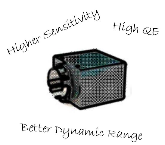
6 advantages of CMOS image sensors vs CCD
There are many advantages of CMOS versus CCDs machine vision cameras outlined below: 1 – Higher Sensitivity due to the latest pixel architecture which is beneficial in lower light applications. 2 – Lower dark noise will contribute to a higher fidelity image. 3 – Pixel well depth (saturation capacity) is improved providing higher dynamic range. 4 – Lower Power consumption. This becomes important as lower heat dissipation equals a cooler camera and less noise. 5 – Lower cost! – 5 Megapixel cameras used to cost ~ $2500 and only achieve 15 fps and now cost ~ $450 with increased frame rates. 6 – Smaller pixels reduce the sensor format decreasing the lens cost.
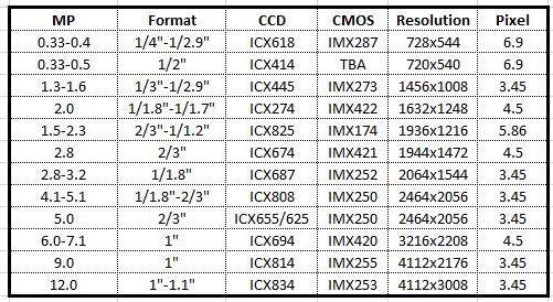
What CMOS image sensors cross over from existing CCD image sensors?
1st Vision’s sales engineers have over 100 years of combined experience to assist in your camera selection. With a large portfolio of lenses, cables, NIC card and industrial computers, we can provide a full vision solution!
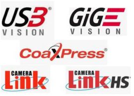
Machine Vision standards have evolved providing defined models of how industrial cameras communicate to a PC allowing easier implementation of machine vision technology. Vision systems can be made up of cameras, frame grabbers and vision libraries from various manufacturers. The vision standards provides compatibility between the various manufacturers for easy implementation.
Machine vision applications require some basic tasks of finding and connecting to the cameras, configuring parameters, acquiring images and dealing with events to and from the cameras.
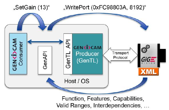
In order to provide cameras from various manufacturers to work together with 3rd party software and hardware from other manufacturers and provide the tasks above, a standard must be followed. “GenICam” is the basis for this standardization, providing compatibility using a Generic Transportation layer and Generic Application programming interface. These are referred to as “GenTL” and “GenAPI” respectively. GenTL provides the communication layer and GenAPI enables camera features to be configured by analyzing a compliant XML file for the camera.
Camera manufacturers however provide unique independent features providing various advantages from one to another. Creating these unique features blur the lines of the standard, not always making a camera fully compatible with another manufacturers software. For example, an industrial camera may use the GenTL layer to be recognized but may have special features making it unique as well.
This can be very confusing to understand! IDS Imaging has a white paper explaining the machine vision interface standardization, GenTL, GenAPI and the system architecture . CLICK BELOW NOW TO DOWNLOAD!
Click to download
1st Vision’s sales engineers have over 100 years of combined experience to assist in your camera selection. With a large portfolio of lenses, cables, NIC card and industrial computers, we can provide a full vision solution!
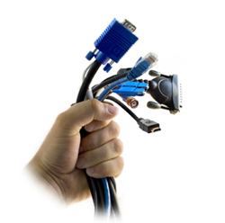
While not an exact figure, we would estimate that about half our client’s problems with machine vision camera connections, dropped frames, etc. comes back to a cabling issue. This is especially true for USB and GigE cameras.
In most of these cases, the issue is that the user is using a poor/low quality cable that was not made for the high speed and/or long distance demands of the application. Most inexpensive camera cables available via mail order are not made for use in high speed highly reliable data transfer applications. If your phone isn’t transferring at the full USB3 bandwidth, you normally don’t care. You probably don’t even know. But when you purchase a high speed USB3 camera and you can’t achieve its full frame rate, or you achieve it intermittently, this becomes a big issue.
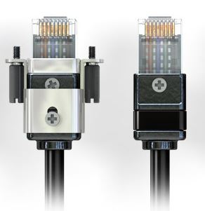
This is the reason 1stVision offers ‘machine vision/industrial’ USB3 and GigE cables. These cables are tested to specs, come with screw locks to prevent the connectors from falling out, use larger gauge wire, are over molded. They are designed to be twisted and bent (somewhat) and are industrial!
Signal amplitude (the voltage of the signal in the cable) is a function of distance and frequency for cables. For instance, Ethernet is specified to 100 meters. So your cable should work when each device is 100 meters away. However, without the proper cable, you will not maintain the full 1000 Mbits/s data transfer rate! You might only be getting 50% of the speed depending upon the distance without a high quality cable.
Finally, consider the cost if your machine vision camera is part of an instrument or product that is being sold to your clients. We see far too many clients who try to save $30 on the cable only to find out that it is costing them thousands of dollars to trouble shoot a problem that can be easily solved with the proper part. Not to mention the cost to their client when the system isn’t working, and a hit to their reputation of not building a reliable system.
Here is our advice:
If you are in an industrial setting, you are compromising the reliability and robustness of your system if you are not using an ‘industrial cable’. Even if you are not operating at maximum speed of the camera, you should have these cables. BTW, these cables are not that much more expensive mail order cables. They are in the 10’s of dollars, but not in the 1’s of dollars.
If you are using USB3 cables, you should really be using ‘industrial’ cables. Current ‘inexpensive’ USB3 cables are not reliable at over 2M, and only 1M for USB C connector types. If you are using USB3 specifically to get the higher speeds from this protocol, then you absolutely need to be using ‘industrial’ cables. Inexpensive cables are not reliable for high speed data transmission.
If you are in a lab environment, with the cable never moving, and only going a short distance, then a high quality ‘inexpensive’ Cat 6e cable will work. There is a difference between inexpensive Ethernet cables. The one that came with the security camera all folder up is NOT what you should use. A reputable mail order cable vendor selling high quality patch cables is OK.
Don’t be penny wise and pound foolish. At 1stVision, we offer these cables not to enrich ourselves, there is not much profit in a $30 cable, but rather to make sure our clients systems work well.
1st Vision’s sales engineers have over 100 years of combined experience to assist in your camera selection. With a large portfolio of lenses, cables, NIC card and industrial computers, we can provide a full vision solution!