![]() There has been a lot written about the ratings of machine vision lenses. 1stVision had created white papers that describe this in detail. However, the lens industry continues to use the marketing term, Megapixel Machine Vision Camera Lenses.
There has been a lot written about the ratings of machine vision lenses. 1stVision had created white papers that describe this in detail. However, the lens industry continues to use the marketing term, Megapixel Machine Vision Camera Lenses.
Let’s get this out of the way right now.
There is NO such thing as a Megapixel Machine vision Camera Lens.
But since it is me against the world, let me explain why sometimes a 12 MP lens is really the same resolution as a 5 MP quality lens.
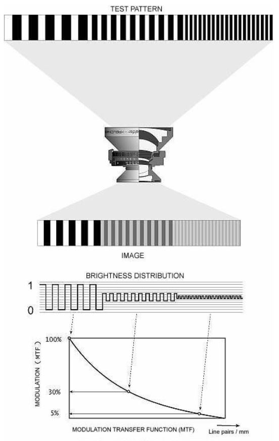
The first thing to understand is that lenses are evaluated on their resolving power, which is a spatial resolution. For lens used in the industrial imaging marketplace, this is normally given in terms as “Line Pairs per mm” (LP/mm). The reason it is expressed this way is because to resolve a pixel of “X” um, you need to use the formula, 1 / 2X where “X” is the pixel size and 2 is the Nyquist limit. So to resolve a pixel of 5um we need a resolution of 1/ ( 5um*2) per line pair. In LP/mm, this becomes 100 LP/mm.
A graph showing a lenses performance is shown in a plot below, plotting intensity vs. LP/mm. This is called the Modulation Transfer Function (MTF). Note that as the LP/mm increases and the lens can’t resolve it as well, the intensity falls off. This measurement is variable to F stop and angle of light, so real MTF charts will indicated these parameters. This is the only real way to empirically evaluate how a lens will perform.
You can visually compare lenses, but to truly compare Brand A vs. Brand B you would have to test them under identical situations. You can’t compare Brand A’s MTF vs. Brand B’s if you don’t know what the parameters used to test them are (need the same camera, with the same lighting, with the same focus, with the same f stop, the same gain, etc. etc.). Unfortunately its very hard to get that information from most lens manufacturers.
1, 3, 5, 9, 12 Megapixel lens?
What does this mean? As an example, Sony has recently introduced a new line of image sensors which have 5MP, 9MP and 12MP sensors. Many clients have called and said, “I want to use the 12MP sensor, so please spec a lens that can do 12MP.” Unfortunately, this isn’t correct as each of these sensors uses a 3.45um pixel. They ALL need the same quality lens! Why? Because it is the size of pixel, what you have to resolve, that dictates the quality of the lens!
In the above situation, the 5MP sensor needs a 2/3” format lens, the 9MP needs a 1” lens, and 12 MP needs a 1.1” format lens. (Multiply the size of the pixel by the number of H and V pixels to get the sensor format – more on format HERE ). However, this sensor needs about 144 LP/mm of resolving power as its a 3.45um pixel size. As much as I detest the nomenclature of “5MP lens” etc., I do appreciate what Fuji does; as they will state, “…. This series of high-resolution lenses deliver 3.45um pixel pitch (equivalent to 5MP) on a 2/3″ sensor”. Now this make more sense!
In turn, if you see a lens stated as a “Megapixel Machine vision” lens, question this! It really needs to be stated in terms of its capability to resolve the pixel size in LP/mm!

1stVision has a staff of machine vision veterans who are happy to explain this in more detail and help you specify the best lens for your application! Contact 1st Vision!
Additional References:
For a comprehensive understanding on “How to Choose a Lens”, download our whitepaper HERE.


 We often are asked the question, “What is the difference between a global and rolling shutter image sensor in