 For most cameras in the automated imaging marketplace, the sensor sizes are 1” and less. (1″ sensors have 16mm image circle/diameters)
Note the size in inches and the image circle size in millimeters do NOT match! 1” does not convert to 16mm!. But that is a topic for another blog post!)
Industrial cameras with C/CS mount sensors normally range from ¼” to 4/3” ( up to 22mm image circle, which is the largest a C mount is by definition).
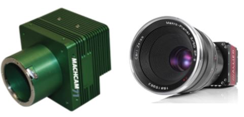
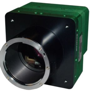
However, there are many cameras that have sensors larger than this, with many being a full 35mm sensor. These sensors typically require larger F or EF mounts as seen in the picture above.
Click here for F-mount lenses from Kowa
Click here for F-mount lenses from Schneider
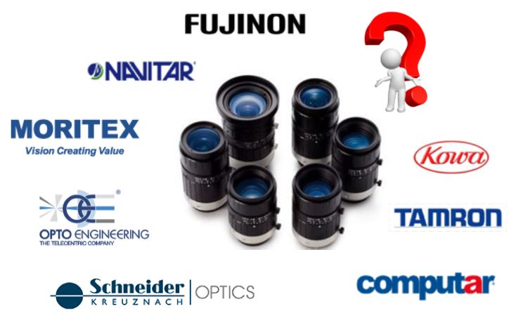
The question becomes, how do you find a suitable lens for these cameras?
First, let address the Issues with F mount lenses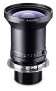
The mount most commonly used by camera vendors for sensors larger than C mount are F mounts. F mounts are most popular mount for SLR cameras, designed by Nikon about 1960. https://en.wikipedia.org/wiki/Nikon_F-mount
F mount lenses for commercial and consumer/prosumer cameras are excellent optically and priced well but there are several issues you need to consider with these lenses for automated imaging applications.
- First, F mount lenses are bayonet, not screw mount. That means they are not as secure as C mount, and therefore, much more prone to vibration, or even coming lose.
- F mount lenses for the consumer/prosumer market are designed to take fantastic color pictures. To do this, the lens coatings are optimized for color. This can affect mono images.
- Consumers want their cameras to be light, so the F mount lenses are made with as much plastic as possible. This is not great for industrial applications
- These lenses are designed for automatic focus and exposure and have controls for that in the lens itself.
- Finally, the last issue is that many of these lenses are designed for the automated controls with prosumer cameras, autofocus and autoexposure.
If you can find an all metal manual F mount lens from 20 to 30 years ago, it would be great for an industrial application! If not, we suggest you turn to one of the companies that make F mount lenses specifically for this market. The major vendors are Schneider, Edmund Optics, and Kowa. All have a series of F mount lenses that are much more rugged than a prosumer F mount lens, and also don’t have the extra controls for automatic focus/iris. They have lock screws as well to hold their settings. The major limitation to these lenses are that they cost more than prosumer lenses, and are in just a small range of focal lengths.
Contact us for further specifications and pricing
EF Lenses
Since many of the new large format lenses can be controlled electronically via 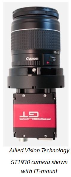 the camera, the automated imaging industry has created several products to use these lenses. The solutions from Birger Engineering, www.birger.com are straightforward to use. They make a mount that attaches to the camera and allows for the use of EF mount lenses. Attached to their mount are connections to drive the lenses, via serial commands with their SW. Several camera manufacturers have built cameras with EF mounts as part of the camera. This is an especially nice solution since there are no wires hanging out for control, and the lens is controlled directly from the camera’s SDK.
This provides a high level overview of the considerations in selecting a lens and size for large format camera sensors. 1st Vision has extensive knowledge with lenses and cameras and will help you in the selection process.
Please contact us and discuss your application with our sales engineer!
Related Blog posts:
Canon EF mount integrated into Allied Visions GT1930L