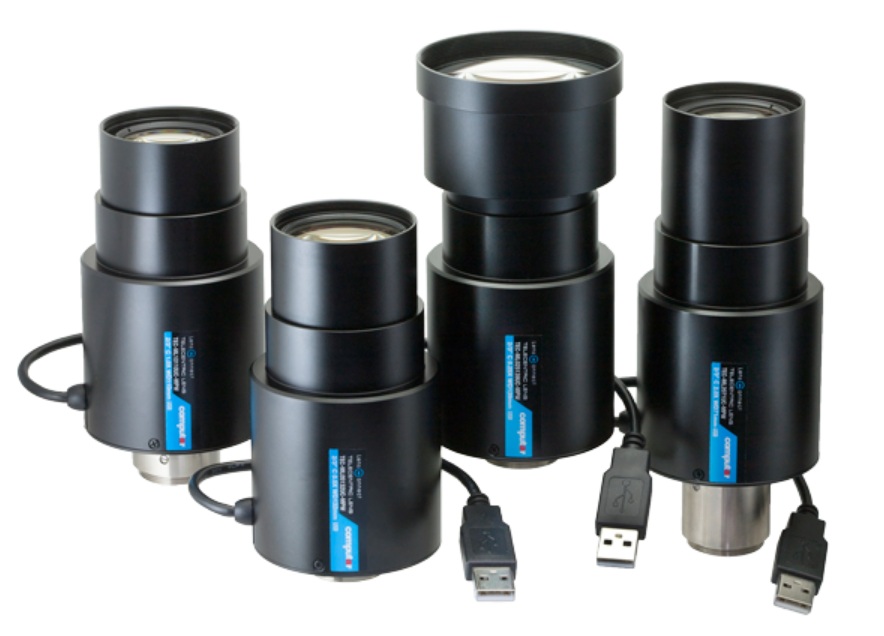
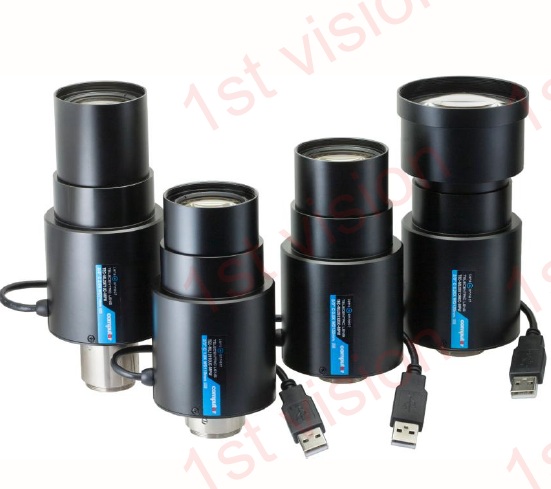
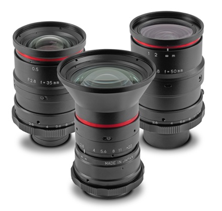
Kowa LF high-resolution large-format machine vision lenses are engineered for rigorous industrial imaging. With a 46.0mm image circle, these optics are optimized for 4K line scan cameras and large-sensor area scan systems.
Two mount options
F-mount or TFL-II mount
- Large image circle options up to approximately 43.3mm to 46mm depending on model.
- For sensors with pixel sizes from 7.5µm on LF line scan models and 3.1µm on CLS color line scan model.
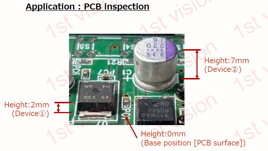
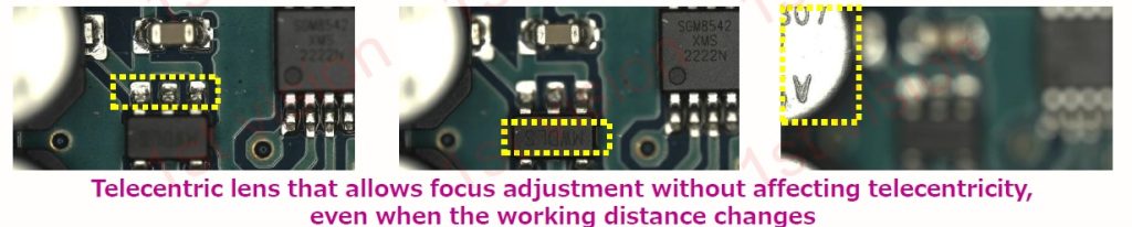
- Very low distortion for web, print, packaging and materials inspection
- Manual focus and iris control.
Noteworthy features
Anti-Rattle F-Mount: Ensures the lens stays locked in place to eliminate image shake in vibration-prone installations.
Enhanced Thumb-Screw Retention: Specialized slide mechanisms prevent thumb screws from working loose, yet allow swift lens removal or changeout as needed.
4K-Ready Optics, Multiple Focal Lengths: Designed for 4K line scan and high-resolution imaging, the LF Series is available in 28 mm, 35 mm, and 50 mm focal lengths for a range of applications.
Industrial reliability: The new ruggedized LF prototypes set a new standard for stability and service life, delivering secure imaging performance under the most demanding circumstances.
Lens selection
If you are a seasoned imaging professional, you may know exactly how to choose the optimal lens, from the large range of available lenses.
Or you may prefer a guided approach.

Or a hybrid approach, using your own review of key considerations in machine vision lens selection, together with our guidance.

1st Vision’s sales engineers have over 100 years of combined experience to assist in your camera and components selection. With a large portfolio of cameras, lenses, cables, NIC cards and industrial computers, we can provide a full vision solution!
About you: We want to hear from you! We’ve built our brand on our know-how and like to educate the marketplace on imaging technology topics… What would you like to hear about?… Drop a line to info@1stvision.com with what topics you’d like to know more about.
#Largeformat
#F-mount
#TFL-II