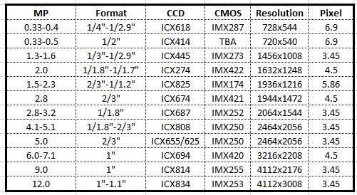
The G-158 camera features the 1.58 megapixel Sony IMX273 image sensor, which has a 3.45 µm pixel size and achieves a frame rate of 75.3 fps. The Manta G-040 camera features the 0.4 megapixel Sony IMX287 image sensor, which has a 6.9 µm pixel size and achieves a frame rate of 286 fps. Higher frame rates can be achieved on both models in burst mode.
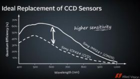
Allied Vision Manta Specifications and comparisons to older Sony CCD sensors as follows:
Allied Vision Manta features include:
Power over Ethernet options (PoE) with Trigger over Ethernet for single cable solutions
Angled Head and Board level variations allowing for custom OEM designs
Video-Iris lens control for challenging lighting conditions
Three look up tables (LUT)
Gige Vision compliant with support for popular third party image processing library’s including Cognex VisionPro, Mathworks, MATLAB and National Instruments
To Learn More about the Allied Vision Manta cameras
View more information on theG-158.
View more information on the G-040.
UPDATE: See this new video from Allied Vision (6/19/18)
1st Vision’s sales engineers have over 100 years of combined experience to assist in your camera selection. With a large portfolio of lenses, cables, NIC card and industrial computers, we can provide a full vision solution!
There has been a lot written about the ratings of machine vision lenses. 1stVision had createdwhite papersthat describe this in detail. However, the lens industry continues to use the marketing term, Megapixel Machine Vision Camera Lenses.
Let’s get this out of the way right now.
There is NO such thing as a Megapixel Machine vision Camera Lens.
But since it is me against the world, let me explain why sometimes a 12 MP lens is really the same resolution as a 5 MP quality lens.
The first thing to understand is that lenses are evaluated on their resolving power, which is a spatial resolution. For lens used in the industrial imaging marketplace, this is normally given in terms as “Line Pairs per mm” (LP/mm). The reason it is expressed this way is because to resolve a pixel of “X” um, you need to use the formula, 1 / 2X where “X” is the pixel size and 2 is the Nyquist limit. So to resolve a pixel of 5um we need a resolution of 1/ ( 5um*2) per line pair. In LP/mm, this becomes 100 LP/mm.
A graph showing a lenses performance is shown in a plot below, plotting intensity vs. LP/mm. This is called the Modulation Transfer Function (MTF). Note that as the LP/mm increases and the lens can’t resolve it as well, the intensity falls off. This measurement is variable to F stop and angle of light, so real MTF charts will indicated these parameters. This is the only real way to empirically evaluate how a lens will perform.
You can visually compare lenses, but to truly compare Brand A vs. Brand B you would have to test them under identical situations. You can’t compare Brand A’s MTF vs. Brand B’s if you don’t know what the parameters used to test them are (need the same camera, with the same lighting, with the same focus, with the same f stop, the same gain, etc. etc.). Unfortunately its very hard to get that information from most lens manufacturers.
1, 3, 5, 9, 12 Megapixel lens?
What does this mean? As an example, Sony has recently introduced a new line of image sensors which have 5MP, 9MP and 12MP sensors. Many clients have called and said, “I want to use the 12MP sensor, so please spec a lens that can do 12MP.” Unfortunately, this isn’t correct as each of these sensors uses a 3.45um pixel. They ALL need the same quality lens! Why? Because it is the size of pixel, what you have to resolve, that dictates the quality of the lens!
In the above situation, the 5MP sensor needs a 2/3” format lens, the 9MP needs a 1” lens, and 12 MP needs a 1.1” format lens. (Multiply the size of the pixel by the number of H and V pixels to get the sensor format – more on formatHERE). However, this sensor needs about 144 LP/mm of resolving power as its a 3.45um pixel size. As much as I detest the nomenclature of “5MP lens” etc., I do appreciate whatFuji does; as they will state, “…. This series of high-resolution lenses deliver 3.45um pixel pitch (equivalent to 5MP) on a 2/3″ sensor”. Now this make more sense!
In turn, if you see a lens stated as a “Megapixel Machine vision” lens, question this! It really needs to be stated in terms of its capability to resolve the pixel size in LP/mm!
1stVisionhas a staff of machine vision veterans who are happy to explain this in more detail and help you specify the best lens for your application! Contact 1st Vision!
Additional References:
For a comprehensive understanding on “How to Choose a Lens”, download our whitepaperHERE.
Many clients call us about doing measurements on grey scale data, but want to use a color machine vision industrial camera because they want the operator or client to see a more ‘realistic’ picture. For instance, if you are looking at PCBs, need to read characters with good precision, but also see the colors on a ribbon cable, you are forced to use a color camera.
In these applications, you could take out a monochrome image from a color sensor for processing, and use the color for cataloging and visualization. But the question is, how much data is lost by using a color camera in mono mode?
First, the user must understand how a color camera works, and how it gets its picture. Non 3-CCD cameras use a Bayer filter, which is a matrix of red, green, and blue filters over each pixel. For each group of 4 pixels, there are 2 greens, 1 red and 1 blue pixel. (The eye being most sensitive in Green, has more to simulate the response).
To get a color image out, each pixel out is a computation of a weighted sum of its nearest neighbor pixels which is known as Bayer interpolation. The accuracy of the color on these cameras is a result of what the original image was, and how the camera algorithms interpolated the set of red, green and blue values for each pixel.
To get monochrome out, one technique is to have the image broken down into Hue, Saturation, and Intensity, with the intensity taken as the grey scale value. Again, this is mathematical computation. The quality of the output is dependent upon the original image and the algorithms used to compute the output.
An image such as the above will give an algorithm a hard time as you are flipping between grey scale values of 0 and 255 for each pixel (assuming the check board lines up with each pixel). Since the output of each pixel is based on it’s nearest neighbors, you could be replacing a black pixel with 4 white ones!
On the other hand, if we had an image with a ramp of pixel values, in other words, each pixel was say 1 value less than the one next to it, the average of the the nearest neighbors would very close to the pixel it was replacing.
What does all this mean in real world applications? Let’s take a look at a 2 images, both from the same brand of camera where one is the using the 5MP Sony Pregius IMX250 monochrome sensor, the other is using the same sensor, but the color version. The images were taken with the same exposure and identical setup. So how do they compare when we blow them up to the pixel level after we take the monochrome output from the color camera and compare it to the monochrome camera?
In comparing the color image (Left), if you expand the picture, you can see that the middle of the E is wider. The transition is not as close to a step function as you would want it to be. The vertical cross section is about 11 pixels with more black than white. Comparing the monochrome image (Right), the vertical cross section is closer to about 8 pixels.
Conclusion:
If you need pixel level measurement, and there is no need for a color image, USE A MONOCHROME MACHINE VISION CAMERA.
If you need to do OCR (as in this example) the above images using color or monochrome would work just fine. This is given you have enough pixels to start and your spatial resolution is adequate.
Do you lose 4x in resolution as some people claim? Not with the image I have used above. Maybe with the checkerboard pattern, but if you can have multiple pixels across your image to measure, you might be ok in with using a color camera and is really application dependent! This post is to make you aware of the resolution loss specifically and 1st Vision can help in making decisions by contacting us for a discussion.
Machine Vision applications required some essentials components and functions. These components will always have a machine vision camera, and typically need lighting with some input and output (I/O) functions to synchronize events in addition to lenses and other accessories.
Industrial PC machine vision computers are also needed to run PC based machine vision software and provide communications between the camera and software. These computers need to be suited for various environments which may be dusty, as in a casting foundry, to full clean rooms in electronics manufacturing. Ideally the computers should help in the overall integration of machine vision applications.
“Machine Vision Computers” are designed specifically for these applications and provide a robust solution!
Introducing Neousys who is a leader in machine vision computing, designed their computer from the ground up for machine vision. This blog post addresses the specific features that are offered and what problems it solves.
What’s really offered in a “Machine Vision” computer? Key features are outlined as follows
Fan-less computer designs: In cases where dust is prevalent, normal computers have fans which brings in dust, clogging fans and creating the system to heat up. Neousys has a fan-less design with efficient heat dissipation allowing for high temperatures from -25 to 70 Deg. C.
Unlike other industrial computer suppliers, Neousys platforms begin with a single board computer laying out all heat generating components evenly, optimizing the thermal design. In turn, at 100% CPU loading, AND at the ends of the specified temperature ranges, there is no performance degradation.
Modular Mezzio cassette design: Application requirements differ from needing multiple communication ports to synchronization of events via inputs and outputs. Neousys provides easy to configure, exchangeable modules to unlock the limits and provide feature expansion. MezIO modules can be added for Power over Ethernet (up to 8+ ports ), USB ports, COM ports (RS232/422/485), Digital IO including encoder inputs or even customized features. All this done with a focus on thermal management.
Integrated Controls: To ensure high quality images, a machine vision system requires accurate interaction between lighting, camera, actuator and sensor devices. Neousys integrates LED lighting controller, camera trigger, encoder input, PWM output and digital I/O, to connect and control all the vision devices. All the vision-specific I/O are managed by Neousys’ patented MCU-based architecture and DTIO/NuMCU firmware to guarantee microsecond-scale real-time I/O control.
Multiple processors architecture: High performance is needed to ensure factory up-time. Neousys provides multiple processors in one computer, such as the CPU, MCU, and GPU (e.g. Nuvis-5306RT, Nuvo-5000E with GPU cassette). Fully customization with specific processors, GPU’s, Memory, Drives (SSD / HDD) are available.
Small form factors: Space is always a constraint to keep products and factory footprints to a minimum. Starting at 4″ x 6″ x 2″, Neousys has machine vision computer offerings to streamline any design.