Many camera manufacturers are now putting up EMVA 1288 data. This is test suite created by the European Machine Vision Association (EMVA) that give you the characteristics and performance of cameras, e.g. S/N ratio, noise, etc. , and there are specifications on how to run the tests.
Please note that there is a significant amount of variance allowed within the tests. Each manufacturer has their own test setup, so comparing sensors or product lines from a specific manufacturer is very appropriate.
Comparing results between different manufacturers, especially looking at small details is NOT appropriate. For instance, if Manufacturer A’s test has a 5% variance on what Manufacturer B’s test is on the same sensor, but the difference between the two manufacturers is 5%, there is no valid conclusion! The result is within the variance. Do NOT get sucked into this comparison war.
The EMVA test produces a 30 page report for each specific camera test, testing is across multiple wavelengths, etc. Results that are given in tabular format with one number for each camera are not really a good picture of the test results to compare across manufacturers.
If you want further details, please contact 1stVision. We have conducted many comparison tests and can provide practical advice and discuss it in context of your application.
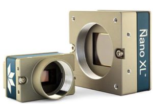
Teledyne Dalsa introduces TurboDrive 2.0 for their Genie Nanos
With the introduction of the Genie Nano came Turbodrive which allowed ‘faster GigE than GigE’ speeds. Turbodrive is a lossless hardware encoding scheme that potentially reduces the amount of data to be transmitted from the camera to the computer. Dalsa’s Nanos, which are priced identical to the competition, offers the users the ability to go faster at no extra cost. Note that the user can turn on or off the encoding.
However, the encoding scheme is data content dependent, and therefore if your data varies a lot within an image the compression is minimal. If your data varies a lot from image to image, then using the encoding means that only certain frames will get a speedup resulting in an inconsistent data transfer rate.
Teledyne Dalsa has just recently introduced TurboDrive 2.0, a firmware upgrade for all Nanos. The major enhancement is that now TurboDrive offers multiple levels of encoding. Level 0 is lossless, and each successive level has some potential lossy amount.
The table below indicates quality level, image compression ratio (absolute worst case scenario) and effective bandwidth gain
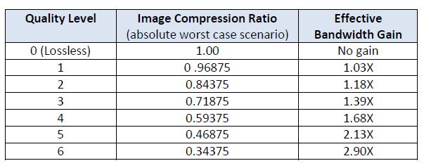
As you can see, at level 6, you have a worst case compression of 0.33, yet a speed up of 3. Note, this is a worst case situation so you might get a speed up of 3x, yet be at 0.8. The algorithm is data dependent! (more about this in the tech primer)
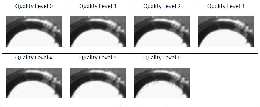
Depending on the application, various compression levels provide minimal degradation. The following images are shown for comparisons using the varying quality levels.
As you can see, even at level 4, there is very little degradation in the image. It is easy to imagine that with this image, you can still do your image processing yet get a speed up of 68%!
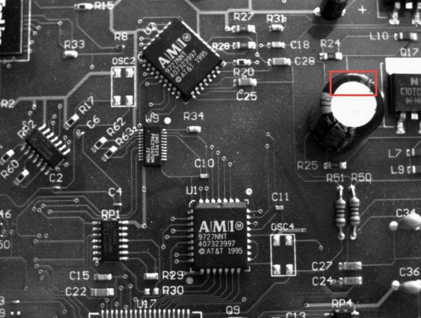
Level 0 “Lossless” to Level 6 indicate the quality level in the images.
Learn more by clicking the icon below for the comprehensive application note!

1stVision has a ton of resources to learn about TurboDrive technology in general. Please visit our dedicated Teledyne Dalsa Turbo Drive resource page HERE
If you have been following Sony’s new IMX image sensor product line, their newest sensors are based on a 3.65um pixel pitch. However, when you scale this up to their new 12MP sensor (Sony Pregius IMX253, IMX304), the sensor size becomes 1.1” (17.6mm diagonal) format. A 1” lens format will not cover this image circle and in turn has vignetting in your image (Read our blog post on sensor size vs. lens size ) .
One possible solution is to use a 1” lens and vignette 5% on each side, or use a 1” lens and stop it down where the vignetting goes away. However this is not an optimal solution. A second solution is to use a F Mount lens, but if the camera is a C mount, you will need a C to F adapter, again less than ideal.
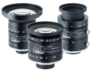
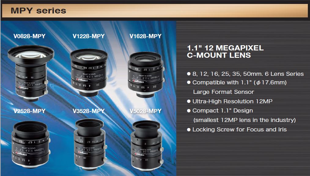
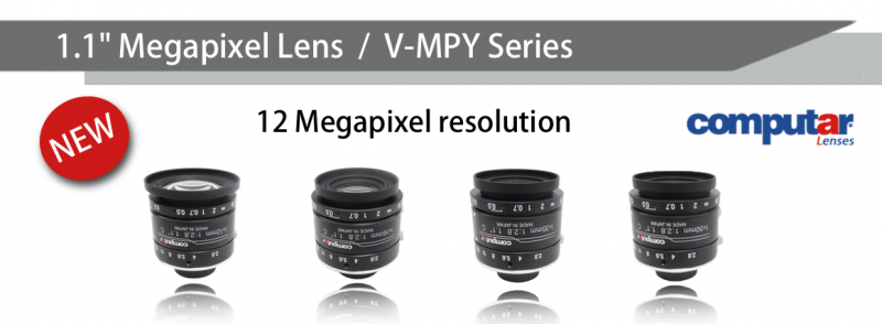
Fortunately there are some C mount lenses that are greater than a 1” image format. Kowa and Schneider both have been shipping 4/3” format lenses, although these are quite expensive. Recently, Computar has come out with a line of 1.1” format lenses SPECIFICALLY for this sensor!
Key Features of the 1.1″ format, Computar MPY 12MP C-mount lenses
1st Vision’s sales engineers specialize in industrial imaging and can help you in the lens selection. Additionally, they can help ensure you have the best lens mated to the newer sensors to ensure the highest contrast.
Common lens questions we are often asked are, “What is a lens’s optical format (or size; we will use the two interchangeably) and how does it relate to specific image sensor sizes in industrial cameras? Along with, “Can any size machine vision camera be used on any lens format or do they need to be matched exactly?”
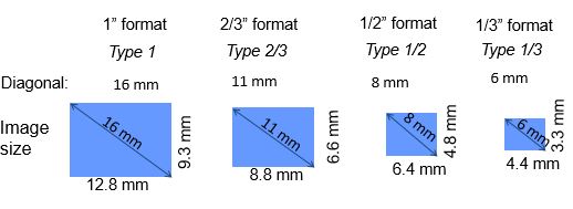
First lets review the sizes of the machine vision camera image sensors themselves (as seen below).
The image sensor size is typically put in terms of “inches”, but really has nothing to do with this and dates back to the “image tube” days. Without a big history lesson, a sensor that fit into an image tube with a 1” (inch) yoke was deemed a 1” image format . Today, we still use these terms and see commons sizes stated as 1/3”, ½”, 2/3” as seen in the image above. Note: The image size in ” does NOT calculate to mm and vice versa! It is nomenclature only.
However, what is important is to look at the diagonal across the given image sensor which is the “image circle”. (i.e The 1/3” format above has a diagonal of 6 mm. )
The size of the lens MUST be equal or greater than the size of the sensor ( circle size that covers the sensor) or you simply will not get the whole image!
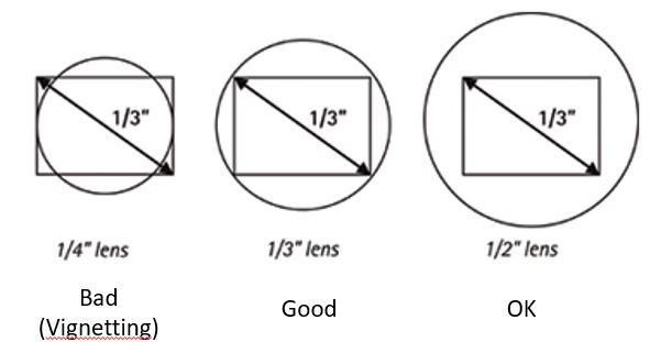
The diagram above shows a 1/3″ format image sensor (6mm diagonal). In order to adequately cover the image sensor, you need a 1/3″ lens format or larger. On the left, we show a lens with a 1/4″ format, and it does not cover the sensor.
The end results from the improper mating of a smaller lens format than the image sensor format will be vignetting (dark corners where the lens does not cover the sensor) of the image.
What can I do when there is no specific lens format matching the image sensor format?
Lens manufacturers are continuing to design lenses to address the changing sensor market. However you will not always find a specific size format to match the lens. In these cases, you just need to ensure the lens format (image circle diameter) is larger than the sensor as mentioned in the above example.
An example is the newer 1/1.2” sensor sizes (IMX174, IMX249 ) which have a diagonal of 13.4mm. Although there are some lens manufacturers that designed a lens with the specific 1/1.2” format, there are not many. Referring to lens format diagram, the 1/1.2” format is between a 2/3” and 1” format. The 2/3” format has a image circle of 11 mm which will not fully cover the 1/1.2” format (13.4mm diagonal), and you will get vignetting of the image. The solution is to use the next size up which is a 1” format. This format is commonly found in many lens manufacturers, in turn providing many lens manufacturers to choose from.
In conclusion, you can use an image format on a lens on smaller image sensor size, but not the other way!.. You’ll have vignetting and lose part of your image!
What else do we need to consider in lens selection?
This blog post simply covers sensor formats vs sensor sizes. There is much more to consider in a lens selection such as resolution of the lens to resolve the pixels themselves, what focal length is needed etc.
Here are some further resources to help in the selection process. Additionally, 1st Vision has over 100 years of combined experience in industrial imaging in which you can contact us to aid in the section.