IDS Software Suite 4.96.1
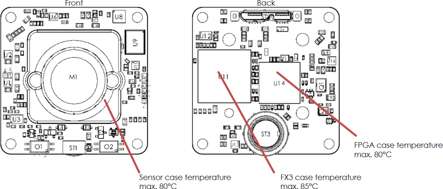
Using the example of the UI-324xLE, the specifications for maximum temperatures, mounting, shield and ESD protection are provided. The listed data is applicable for all USB 3 uEye LE board level versions.
Temperature management

Fig. 415: Temperature information
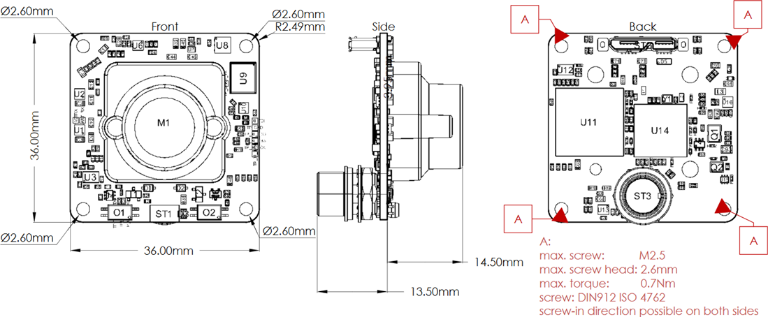
Assembly information
The USB 3 uEye LE cameras can be screwed on both sides.

Fig. 416: Mounting details
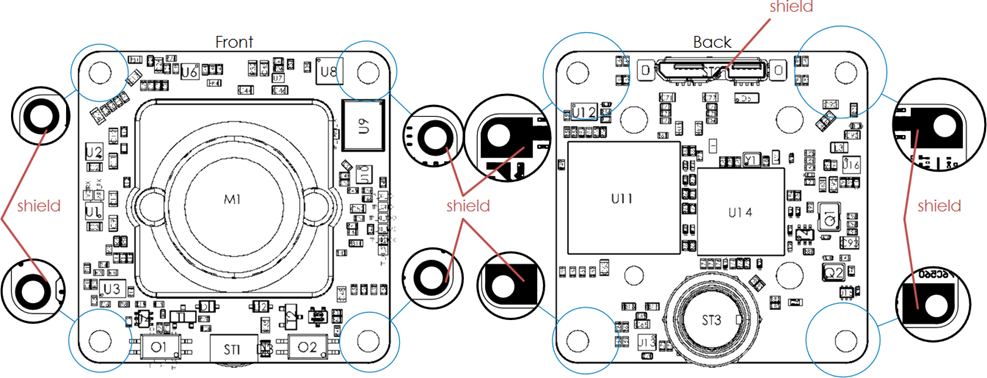
Assembly hole attachment

Fig. 417: Assembly hole attachment
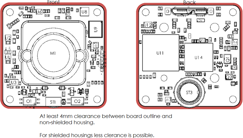
ESD protection
•For optimum ESD protection, keep a clearance on all sides of 4 mm from unshielded housings. A smaller clearance is possible with shielded housings.
•The PCB should be mounted with the fixing screws on a base connected to the shield. If this is not possible, an insulating connection must be ensured.
•The connection cable should have a shield with low-resistance on both sides.

Fig. 418: ESD protection