IDS Software Suite 4.96.1
The optional "motherboard" version of the GigE uEye LE with ZIF plug offers even greater flexibility. A wide range of remote boards with RJ45 ports can be connected via Flex ribbon cables.
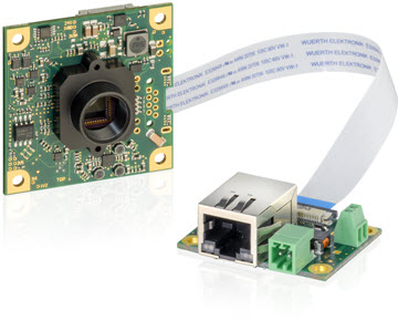
Fig. 607: Motherborad version of GigE uEye LE
 |
The applicable tolerances for the overall dimensions of PCBs are higher than the tolerances for housing dimensions. |
 |
NOTICE! Make sure to avoid mechanical or electrical damage of the printed circuit board or its connections. Do not touch the printed circuit board while it is powered. Always hold the board by the edges to avoid the risk of electrostatic discharge damage. |
All four mounting holes of the camera are potential free and have no connection to shield or ground.
Mechanical data of the motherboard version
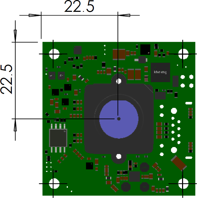 Fig. 608: GigE uEye LE motherboard with S-mount - front view |
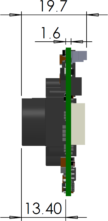 Fig. 609: GigE uEye LE motherboard with S-mount - side view |
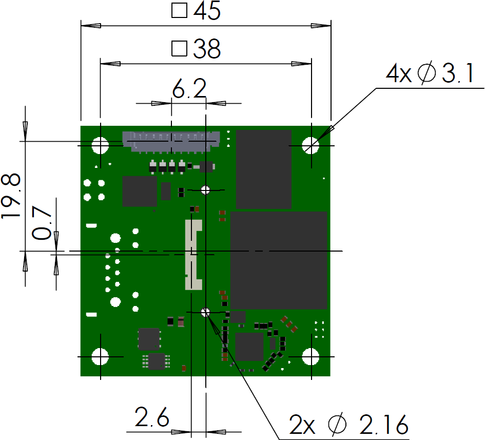 Fig. 610: GigE uEye LE motherboard with S-mount - back view |
|
Mechanical data of the optional daughterboard
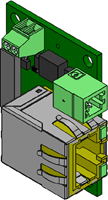 Fig. 611: GigE uEye LE daughterboard |
|
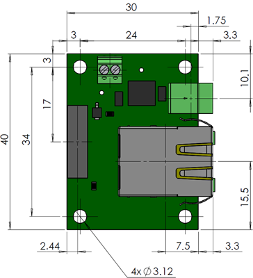 Fig. 612: GigE uEye LE daughterboard - back view |
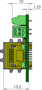 Fig. 613: GigE uEye LE daughterboard - side view |
Technical data
The 20-pin ZIF connecting plug (Omron XF2J20) has the following pin assignment:
Pin |
Description |
Note |
|---|---|---|
1 |
Ethernet LED 5 |
LED 1 (green/orange) |
2 |
Ethernet LED 6 |
|
3 |
VIN +12 – 24 V DC |
VCC external, 12 – 24 V |
4 |
VIN +12 – 24 V DC |
|
5 |
Ground (GND) |
GND external |
6 |
Ground (GND) |
|
7 |
MDI3 P |
GigE Pair 3 |
8 |
MDI3 N |
|
9 |
Ground (GND) |
|
10 |
MDI1 N |
GigE Pair 1 |
11 |
MDI1 P |
|
12 |
Ground (GND) |
|
13 |
MDI0 P |
GigE Pair 0 |
14 |
MDI0 N |
|
15 |
Ground (GND) |
|
16 |
MDI2 P |
GigE Pair 2 |
17 |
MDI2 N |
|
18 |
Ground (GND) |
|
19 |
Ethernet LED 3 |
LED 2 (yellow) |
20 |
Ethernet LED 4 |
The pin assignment of the I/O connector is described in the GigE uEye LE pin assignment I/O connector chapter.
Power supply of the daughterboard
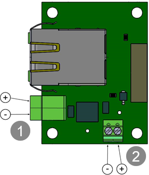
Fig. 614: Power supply via one of the two Phoenix connectors
1.Phoenix Contact COMBICON MC PCB terminal block header right angled, 2 way/1 row, 2.5mm pitch, solder connection, 4A (1881448)
2.Screw terminal
Separate daughterboard
Note the following points when you develop your own daughterboard:
•The camera can be powered completely via the ZIF connecting plug.
•Any necessary reverse polarity protection, overvoltage protection, or filtering the supply voltage must be installed on the daughterboard.
•The Ethernet connection is also done via the ZIF connecting plug.
•On the daughterboard a Magnetics is required. Here, the following type should be used as it fits to the used PHY:
Magnetics manufacturer: HALO item no.: TG111-S12NYNRL
If another type is used, this may lead to failures in the Ethernet connection.
•For the RJ45 socket, another socket can be used. The following standard socket is used:
RJ45 socket manufacturer: AMP item no.: 6-1734324-3