IDS Software Suite 4.96.1
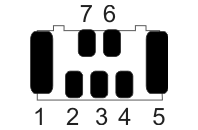
Alternative USB connector on the USB uEye LE PCB version
|
The following specifications apply to the board level versions of the USB uEye LE. The inputs/outputs mentioned are not accessible in the housing versions. |
Pin |
Description |
USB cable (standard color) |
 Fig. 485: Pin assignment of the USB connector - view PCB bottom |
|---|---|---|---|
1 |
Cable shield |
- |
|
2 |
Power supply (VCC) 5 V |
red |
|
3 |
Data (+) |
green |
|
4 |
Ground (GND) |
black |
|
5 |
Cable shield |
- |
|
6 |
Not connected |
- |
|
7 |
Data (-) |
white |
Alternative USB connector on the UI-149xLE PCB version
|
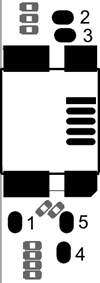
The board level version of the UI-149xLE has not been prepared for use of a standing USB connector. The board provides five additional connection points to which a USB cable can be soldered if required. These are located next to the lying USB 2.0 mini-B connector. |
Pin |
Description |
USB cable (standard color) |
 Fig. 486: UI-149xLE PCB version - additional USB connector |
|---|---|---|---|
1 |
Cable shield |
- |
|
2 |
Data (+) |
green |
|
3 |
Data (-) |
white |
|
4 |
Power supply (VCC) 5 V |
red |
|
5 |
Ground (GND) |
black |
