IDS Software Suite 4.96.1
GPIO specifications
The two GPIOs (General Purpose I/O) can be used as inputs or outputs. This selection is made by software using the corresponding SDK API functions. Please observe the following criteria:
•Input: 3.3 V, max. input voltage 4.0 V
•Output: 3.3 V, max. 8 mA
|
Min. |
Max. |
|
|---|---|---|---|
Output level "Low" |
0 |
0.8 |
V |
Output level "High" |
2.4 |
3.3 |
V |
Output current |
0 |
8.0 |
mA |
Input level "Low" |
0 |
0.8 |
V |
Input level "High" |
2.0 |
4.0 |
V |
|
NOTICE! The General Purpose I/Os are not potential-free and have no protective circuit. Faulty wiring (overvoltage, undervoltage or inverting the wiring when used as serial interface) can result in a damage in the electronics. During operation as serial interface only LVCMOS levels are allowed to the connector pins. To get a serial RS-232 compliant interface, an external level shifter (LVCMOS/RS-232) is required. Applying RS-232 levels directly to the pins as well as mixing up the signals RxD and TxD can destroy the camera electronics! |
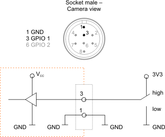
GPIO wiring as input

Fig. 445: GPIO input
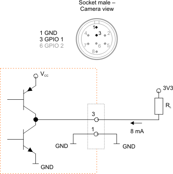
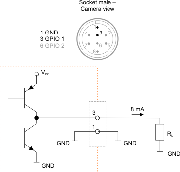
GPIO wiring as output

Fig. 446: GPIO output (1)

Fig. 447: GPIO output (2)
