IDS Software Suite 4.96.1
The specifications for maximum temperatures, mounting, shield and ESD protection are provided. The listed data is applicable for all uEye SE USB 3.1 Gen 1 board level versions.
Temperature management
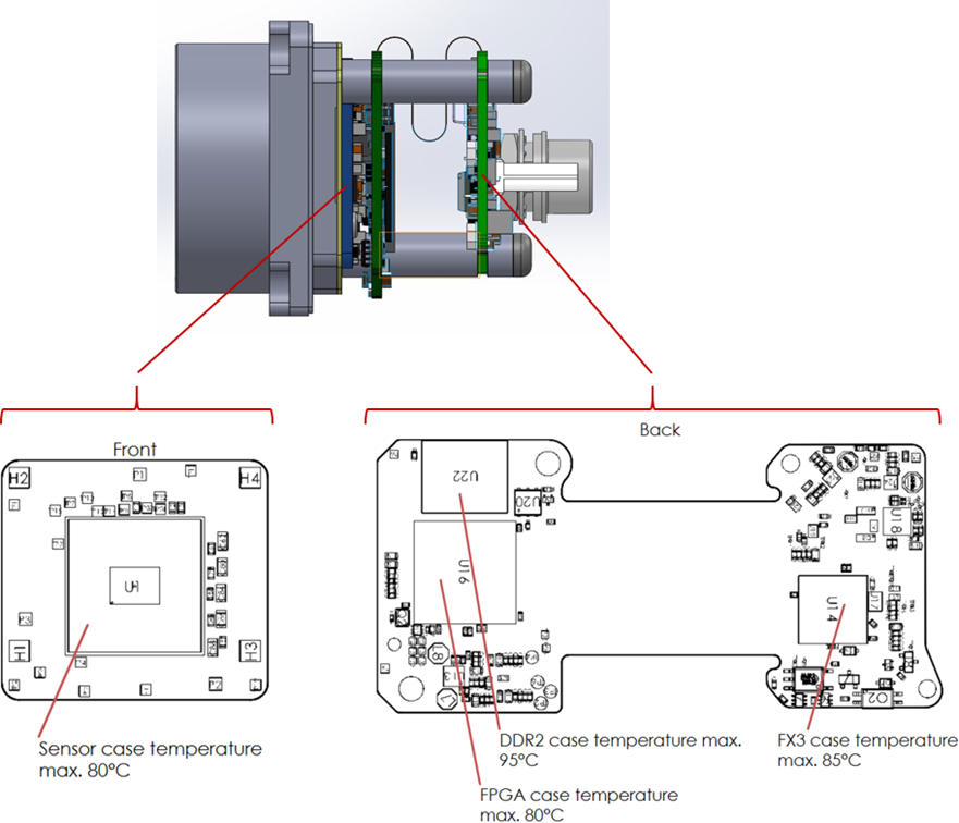
Fig. 354: Temperature information
Assembly information
The uEye SE USB 3.1 Gen 1 board level version with front can either be assembled using the two holes on the underside of the front or using the four holes on the front panel. Attaching the front to the camera shield is only possible with the two options shown.
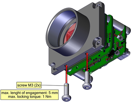
Fig. 355: Mounting via front (1)
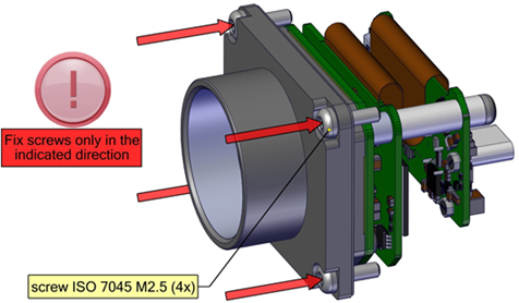
Fig. 356: Mounting via front (2)
For versions without front, assembly is possible using two screws from the rear through the board level. Depending on the sensor, it is distinguished between models with S-board and L-board.
The following figure shows the assembly with S-board. The transport protection (two nuts and locking plate) must be removed first. The sensor board can then be separated from the board level and assembled. The board level is then re-fitted on the sensor board and screwed on.

Fig. 357: PCB version with S-board
The following figure shows the assembly with L-board.
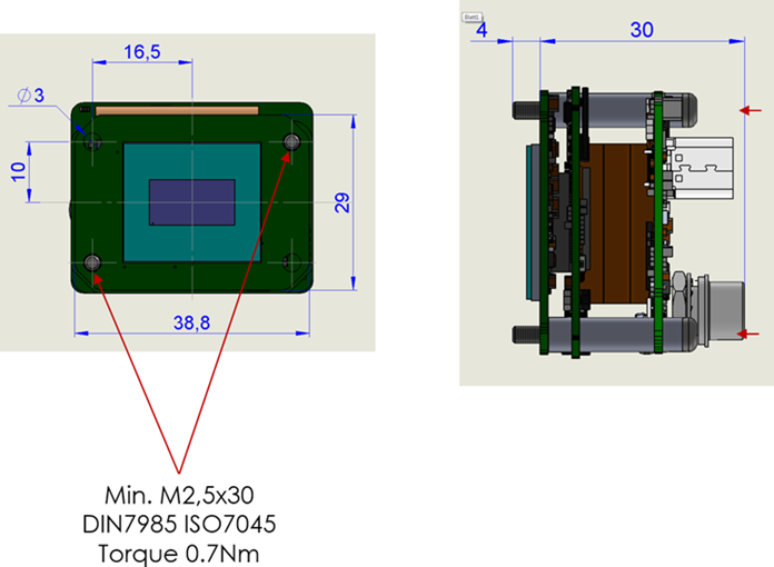
Fig. 358: PCB version with L-board
ESD protection
•For optimum ESD protection, keep a clearance on all sides of 4 mm from unshielded housings. A smaller clearance is possible with shielded housings.
•The PCB should be mounted with the fixing screws on a base connected to the shield. If this is not possible, an insulating connection must be ensured.
•The connection cable should have a shield with low-resistance on both sides.
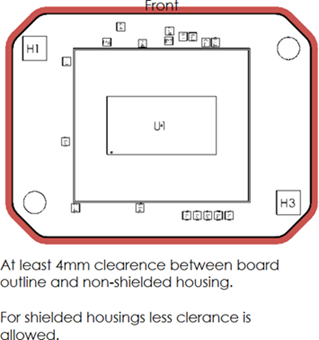
Fig. 359: ESD protection