IDS Software Suite 4.96.1
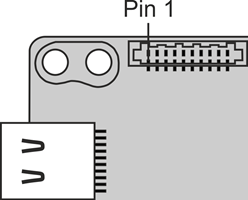
The following specifications apply to the board level versions of the uEye LE USB 3.1 Gen 1. The inputs/outputs mentioned are not accessible in the housing versions.
10-pin header (Molex IllumiMate™ 1041411010)
Pin |
Description |
 Fig. 344: uEye LE USB 3.1 Gen 1 PCB version - I/O connector |
|---|---|---|
1 |
Voltage output •Without USB Power Delivery: 5 V, max. 400 mA •With USB Power Delivery: 5 – 15 V, max. 1 A |
|
2 |
Ground (GND) |
|
3 |
General purpose I/O (GPIO) 2, 3.3 V |
|
4 |
General purpose I/O (GPIO) 1, 3.3 V |
|
5 |
TWI (Two Wire Interface) clock signal (internal 10k pull-up to 3.3 V) |
|
6 |
TWI (Two Wire Interface) data signal (internal 10k pull-up to 3.3 V) |
|
7 |
Trigger input without optocoupler 3.3 V |
|
8 |
Flash output without optocoupler 3.3 V |
|
9 |
Ground (GND) |
|
10 |
Voltage output 3.3 V, max. 300 mA ± 10 % |
* This voltage depends on the supply voltage required for the sensor used.
You can check the color assignment of the cable on the Website directly at the specific accessory item.
 |
The maximum length of the I/O cable is 30 m. The cable must be shielded. |
Power supply
The camera is supplied with power via the USB 3.0 interface. For information on the camera's power consumption, please refer to the Camera and sensor data section.
Note on Power Delivery
There are only the voltages available on the camera that are offered by the host PC. If you switch from a higher voltage to a lower voltage during operation, the camera will do a reconnect.
TWI (Two Wire Interface) operation
The TWI (Two Wire Interface) is operated with a clock frequency of approx. 400 kHz. Multi master mode is not allowed on the TWI while the uEye LE USB 3.1 Gen 1 camera is used.