IDS Software Suite 4.96.1
Digital input specification
|
Symbol |
Min. |
Typ. |
Max. |
Unit |
|---|---|---|---|---|---|
Input high range |
VIH |
5 |
- |
24 |
V |
Input low range |
VIL |
0 |
0 |
1 |
V |
Input leakage current |
II |
- |
- |
- |
µA |
Trigger pulse width (edge) |
|
10 |
- |
- |
µs |
Trigger edge steepness |
|
35 |
- |
- |
V/ms |
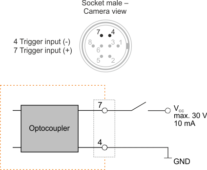
For interpreting the trigger signal, either the rising or the falling edge can be used. The digital input is galvanically isolated using an optocoupler to protect the camera and the PC against surges. Only DC voltages may be applied to the digital input.
Digital input wiring

Fig. 364: Wiring of the digital input (trigger)