IDS Software Suite 4.96.1
GPIO specifications
The two GPIOs (general purpose I/O) can be used as inputs or outputs. This selection is made by software using the corresponding SDK API functions. Please observe the following criteria:
•Input: 3.3 V, max. 5.0 V input voltage
•Output: 3.3 V, max. 4.0 mA (UI-122xLE/UI-124xLE/UI-125xLE/UI-125xLE/UI146xLE/UI-154xLE)
•Output 3.1 V, max. 4.0 mA (UI-164xLE)
•Output 3.0 V, max. 4.0 mA (UI-148xLE/UI-149xLE/UI-155xLE/UI-158xLE)
|
Min. |
Max. |
|
|---|---|---|---|
Output level "Low" |
0 |
0.8 |
V |
Output level "High" |
2.0 |
3.0/3.1/3.3 |
V |
Output current |
|
4 |
mA |
Input level "Low" |
0 |
0.8 |
V |
Input level "High" |
2.0 |
5.25 |
V |
Input current |
|
10 |
µA |
|
NOTICE! The General Purpose I/Os are not potential-free and have no protective circuit. Faulty wiring (overvoltage, undervoltage) can result in a damage in the electronics. |
Internal supply voltage by sensor type
3.0 V |
3.1 V |
3.3 V |
|---|---|---|
UI-148xLE UI-149xLE UI-155xLE UI-158xLE |
UI-164xLE |
UI-122xLE UI-124xLE UI-125xLE UI-146xLE UI-154xLE |
GPIO wiring
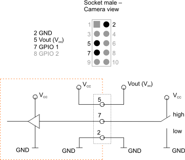
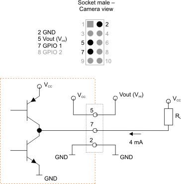
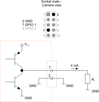
The following figures illustrate GPIO wiring examples.

Fig. 491: GPIO wired as an input

Fig. 492: GPIO wired as an output (1)

Fig. 493: GPIO wired as an output (2)
