IDS Software Suite 4.96.1
Digital output specifications
|
Max. |
|
|---|---|---|
Output current (short-time) |
4.0 |
mA |
Output current (permanent) |
4.0 |
mA |
Output voltage |
3.0/3.1/3.3* |
V |
Breakdown voltage |
not applicable (no optocoupler) |
V |
Collector power dissipation |
not applicable (no optocoupler) |
mW |
* This voltage depends on the supply voltage required for the sensor used (see table below)
|
NOTICE! The digital output of the USB uEye LE is not potential-free and has no protective circuits. |
Internal supply voltage by sensor type
3.0 V |
3.1 V |
3.3 V |
|---|---|---|
UI-148xLE UI-149xLE UI-155xLE UI-158xLE |
UI-164xLE |
UI-122xLE UI-124xLE UI-125xLE UI-146xLE UI-154xLE |
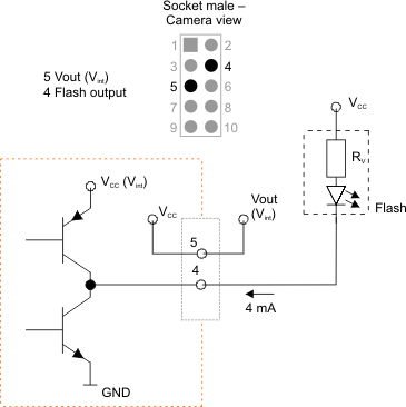
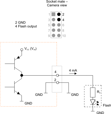
Digital output wiring

Fig. 489: Wiring of the digital output (flash) - inverted logic

Fig. 490: Wiring of the digital output (flash) - non-inverted logic
