IDS Software Suite 4.96.1
GPIO specifications
The two GPIOs (general purpose I/O) can be used as inputs or outputs. This selection is made by software using the corresponding SDK API functions. Please observe the following criteria:
|
Symbol |
Min. |
Typ. |
Max. |
Unit |
|---|---|---|---|---|---|
IO voltage range |
VCCIO |
0 |
- |
3.15/3.3 (see below) |
V |
Input high range |
VIH |
2.0 |
- |
3.15/3.3 (see below) |
V |
Input low range |
VIL |
0 |
- |
0.15 |
V |
Input leakage current |
II |
- |
- |
500 |
µA |
Output high range |
VOH |
2.2 |
- |
3.15/3.3 (see below) |
V |
Output low range |
VOL |
0 |
- |
0.4 |
V |
Output current high |
IOH |
- |
- |
4.0 |
mA |
Output current low |
IOL |
-1.0 |
- |
- |
mA |
|
NOTICE! The general purpose I/Os of the USB 3 uEye LE are not potential-free and has no protective circuits. |
Internal supply voltage by sensor type
3.15 V |
3.3 V |
|---|---|
UI-348xLE UI-358xLE |
UI-324xLE UI-325xLE UI-359xLE |
GPIO wiring
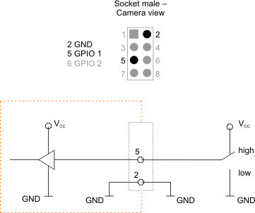
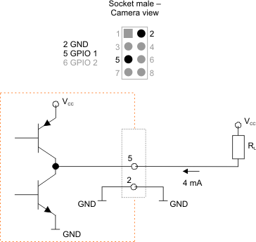
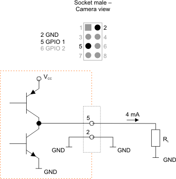
The following figures illustrate GPIO wiring examples.

Fig. 426: GPIO wired as an input

Fig. 427: GPIO wired as an output (1)

Fig. 428: GPIO wired as an output (2)
