IDS Software Suite 4.96.1
In trigger mode, the sensor is on standby and starts exposing on receipt of a trigger signal. A trigger event can be initiated by a software command (software trigger) or by an electrical signal via the camera’s digital input (hardware trigger).
This chapter describes the different trigger modes you can use with the uEye cameras. To choose a mode, go to the camera properties of the uEye Cockpit application or use the API command.
|
Note on the schematic diagrams These illustrations show a schematic view of the image capture sequence. The sensor exposure and readout times and the transmission times depend on the camera model and settings. The pre-processing time depends on the API functions you are using (e. g. color conversion, edge enhancement). For more information on flash timing see the Digital inputs/outputs chapter. |
Software trigger mode
When this mode is enabled, calling the "Snap" function triggers the capture of an image, which is then transferred to the PC. If you call the "Live" function in this mode, the image capture is triggered continuously and images are transferred continuously.

Fig. 3: Software trigger mode with continuous image capture
* Optional flash function. See also Digital inputs/outputs
Hardware trigger mode
When this mode is enabled, calling the is_FreezeVideo() (Snap) function makes the camera ready for triggering just once. When the camera receives an electrical trigger signal, one image is captured and transferred.
If you call the is_CaptureVideo() (Live) function, the camera is made ready for triggering continuously. An image is captured and transferred each time an electrical trigger signal is received; the camera is then ready for triggering again (recommended procedure).
|
When you use triggered image capture, the camera is only ready to process the next trigger signal after completion of the data transfer to the PC. Trigger events that occur during image exposure or data transfer are ignored. An internal counter records the number of ignored trigger events and can be read out from the PC. Where supported, an overlap trigger mode allows overlapping the trigger for a new image capture with the readout of the previous image (see Camera and sensor data). |

Fig. 4: Hardware trigger mode with continuous image capture
* Optional flash function. See also Digital inputs/outputs
Frame rate in trigger mode Camera and sensor data
With many sensors, the maximum frame rate is lower in trigger mode than in freerun mode because these sensors expose and transfer sequentially. Which frame rate is possible in trigger mode therefore depends on the exposure time. The time required for capturing a frame in trigger mode can be approximated with the following formula:
Example: At the maximum exposure time, the frame rate is about half as high as in freerun mode; at the minimum exposure time, the frame rate is about the same.
Frame rate in overlap trigger mode
Some sensors support an overlap trigger mode (see Camera and sensor data). This feature allows overlapping the trigger for a new image capture with the readout of the previous image. These sensors provide almost the same frame rate in trigger mode as in freerun mode.
With these sensors, the maximum possible frame rate in trigger mode is independent of the exposure time. As in freerun mode, the maximum frame rate is set with the is_SetFrameRate() function. To achieve long exposure times in trigger mode, set a low frame rate. (Note that the possible exposure time range depends on the pixel clock and frame rate. A low frame rate setting allows long exposure times. A high frame rate setting reduces the maximum possible exposure time.)
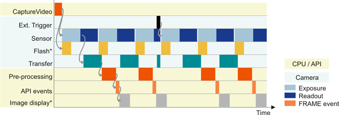
In this mode, cameras running in freerun mode (live mode, see above) can be synchronized with an external trigger signal. The cameras still remain in freerun mode. The trigger signal stops and restarts the current image capture process. You can use this mode to synchronize multiple cameras that you are operating in the fast live mode. Not all camera models support this mode.
|
The freerun synchronization mode is currently only supported by camera models UI-146x/UI-546x. |

Fig. 5: Freerun synchronization with hardware trigger
* Optional flash function. See also Digital inputs/outputs
See also: •Basics: Freerun mode •Basics: Digital inputs/outputs •uEye Cockpit: Trigger •Programming: Using the camera memory (GigE uEye cameras) Programming: |
