IDS Software Suite 4.96.1
 |
NOTICE! Make sure to avoid mechanical or electrical damage of the printed circuit board or its connections. Do not touch the printed circuit board while it is powered. Always hold the board by the edges to avoid the risk of electrostatic discharge damage. |
 |
The applicable tolerances for the overall dimensions of PCBs are higher than the tolerances for housing dimensions. |
|
The board level version of the UI-149x-LE has not been prepared for use of a vertical USB connector. The board provides five additional connection points to which a USB cable can be soldered if required (see USB uEye LE: Pin assignment of the USB connector). |
|
Use only screws with a head diameter of max. 4 mm for the mounting holes of the lens holder. |
Lens mount |
Weight |
|---|---|
S-Mount lens holder |
16 g (incl. S-Mount lens holder) |
- |
12 g (PCB version) |
 |
NOTICE! The camera connectors may be damaged if you install or remove the camera with plugged in cables. Therefore, first unplug the GigEUSB and/or I/O cable from the camera. |
Dimensions of the board level version
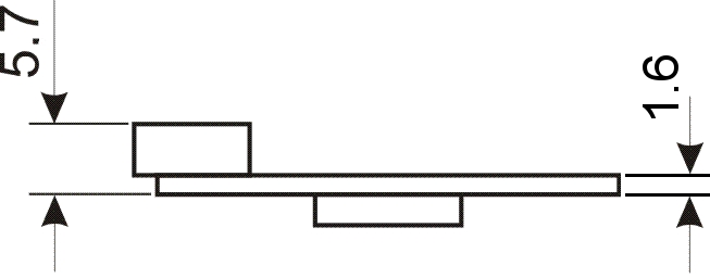 Fig. 457: USB uEye LE USB connector - horizontal position (default) |
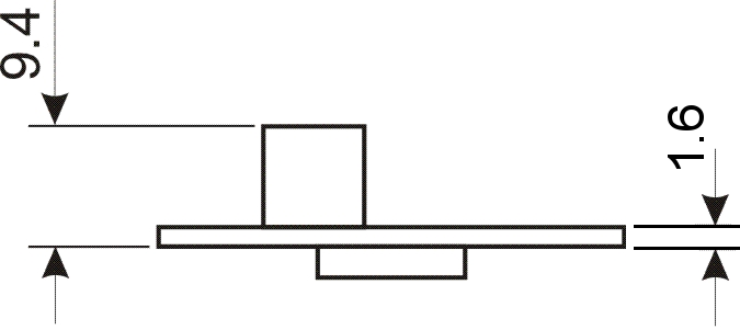 Fig. 458: USB uEye LE USB connector - vertical position (project-related option) |
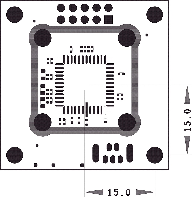 Fig. 459: USB uEye LE PCB version - top view |
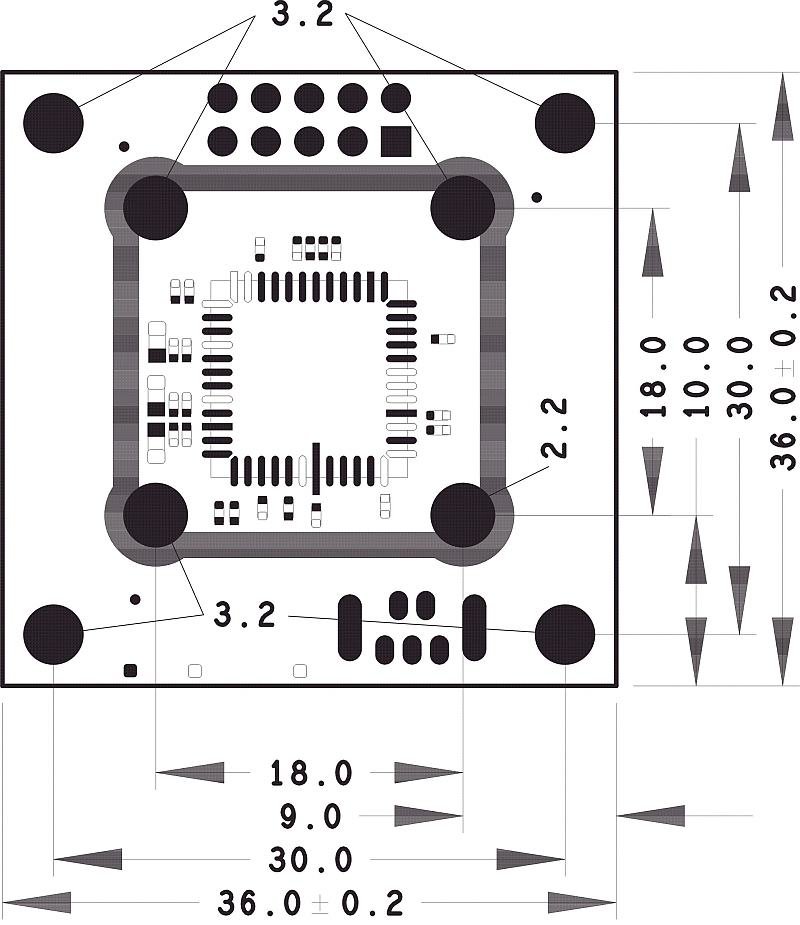 Fig. 460: USB uEye LE PCB version - top view |
|
The optical center of the USB uEye LE PCB version is exactly the center of the board. Note that the holes for mounting the lens holder are not symmetrical to the optical center. They are moved in one direction by 1 mm (see drawing right above). |
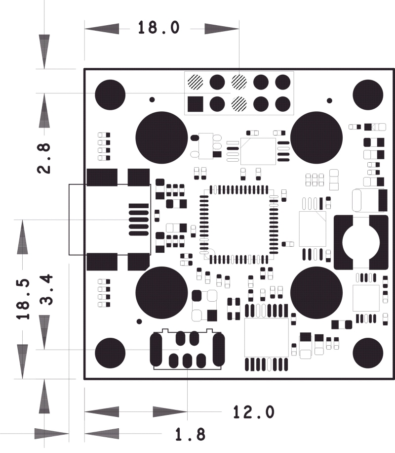 Fig. 461: USB uEye LE PCB version - bottom view |
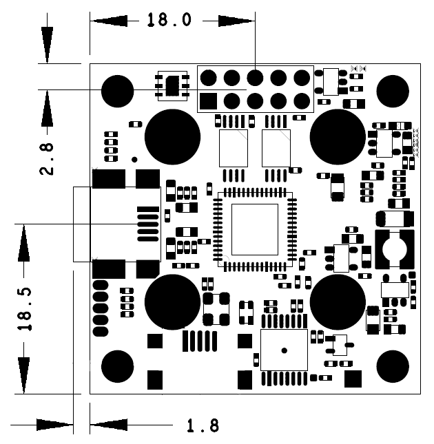 Fig. 462: UI-149x-LE PCB version - bottom view |
Dimensions of the S-mount lens holder (only USB uEye LE board level version)
|
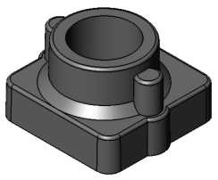
The default lens holder for the PCB version of the USB uEye LE is the M12 lens holder. |
 |
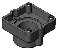 |
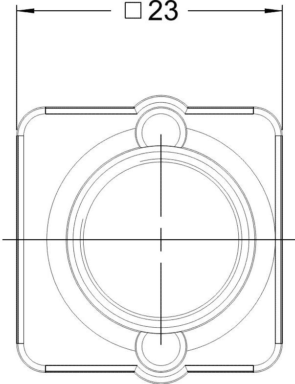 Fig. 463: USB uEye LE lens holder - top view |
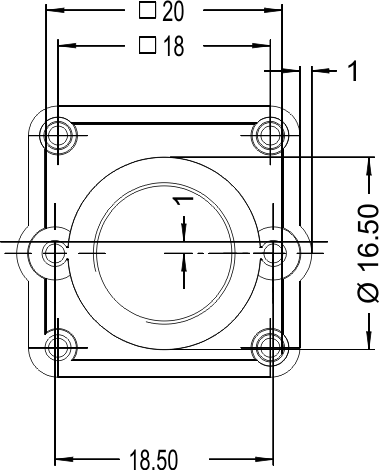 Fig. 464: USB uEye LE lens holder - bottom view |
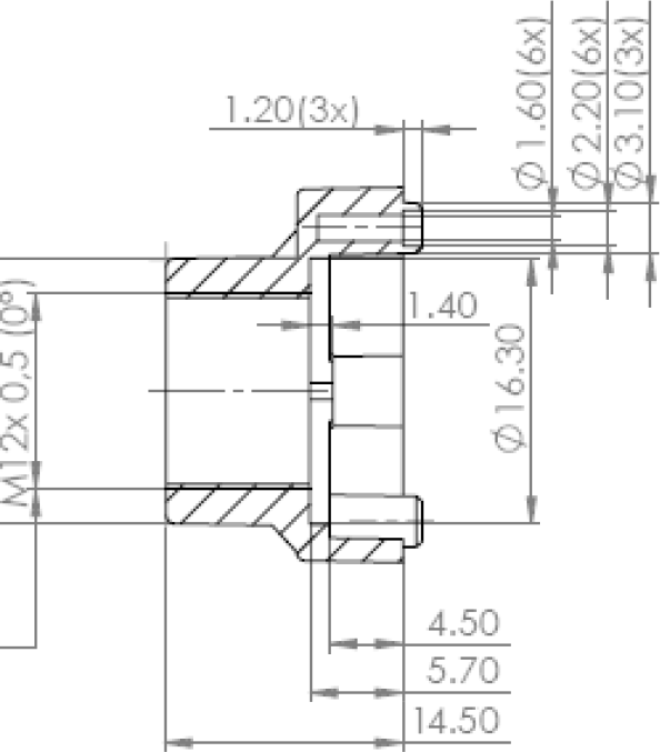 Fig. 465: USB uEye LE lens holder M12 |
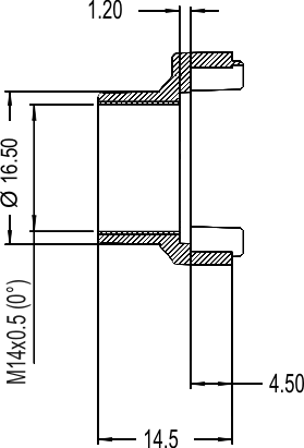 Fig. 466: USB uEye LE lens holder M14 |