IDS Software Suite 4.96.1
 |
NOTICE! Make sure to avoid mechanical or electrical damage of the printed circuit board or its connections. Do not touch the printed circuit board while it is powered. Always hold the board by the edges to avoid the risk of electrostatic discharge damage. |
The USB uEye LE camera are optionally available with a LED lighting board.
In its standard configuration, the LED lighting board features 6 white LEDs. You can control the brightness of the LEDs using I2C commands. Using the digital output (flash) you can enable or disable all LEDs at once.
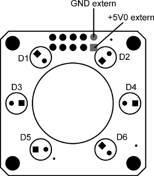
Each 3 LEDs are combined to a group (i.e. LEDs 1, 3, 5 are a group and LEDs 2, 4, 6 are another group). You can adjust the brightness of every group separately. The three LEDs in one group have the identical brightness.
The LED lighting board is connected to the USB uEye LE via a 10 pin socket connector. The pin assignment of this connector is described in the USB uEye LE pin assignment I/O connector chapter.
Mechanical data

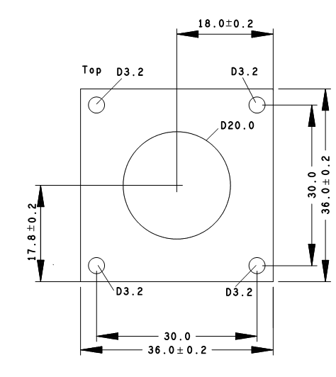
Fig. 467: USB uEye LE with lighting board (view from bottom)

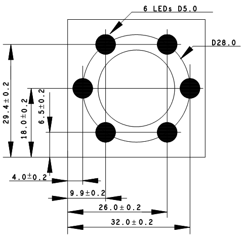
Fig. 468: USB uEye LE with lighting board (view from top)
 |
NOTICE! The camera connectors may be damaged if you install or remove the camera with plugged in cables. Therefore, first unplug the GigEUSB and/or I/O cable from the camera. |
Technical data
Additional power consumption via USB |
max. 488 mA (for 6 LEDs) |
LED |
Ledman LL1503HGWW1-501 |
Operating temperature range* |
-20° C up to +75° C |
Viewing angle |
50° (per LED) |
Color temperature |
6500 K |
Maximum intensity |
6000 mcd (per LED) |
* Please observe the permitted ambient conditions for the camera.
Additional power consumption of the lighting board:
Setting value group 1 |
Setting value group 2 |
Additional power consumption (mA) |
|---|---|---|
00d |
00d |
0 |
95d |
00d |
7 |
105d |
00d |
46 |
115d |
00d |
82 |
125d |
00d |
116 |
135d |
00d |
154 |
145d |
00d |
189 |
95d |
95d |
14 |
105d |
105d |
92 |
115d |
115d |
164 |
125d |
125d |
132 |
135d |
135d |
308 |
145d |
145d |
378 |
Depending on the power consumption of the base camera (see Camera and sensor data), it can happen that the maximum power of a USB 2.0 port (500 mA) is not sufficient to operate the camera and the lighting board.
In this case, either the camera can be connected to two USB 2.0 ports via a Y-cable or you can use the lighting board version which allows an external power supply.

Fig. 469: External power supply of the lighting board
Software functions
To control the brightness of the LEDs via the I2C bus the uEye SDK offers the functions is_WriteI2C() and is_ReadI2C(). The I2C bus can also be accessed using the uEye Cockpit (Properties > Miscellaneous).
The I2C parameters for setting the brightness are:
|
Device address |
Device address |
Register address |
Data value |
|---|---|---|---|---|
LED D1/D4/D5 |
168 |
167 |
0 |
Brightness 95…145 |
LED D2/D3/D6 |
168 |
167 |
1 |
|
Use the SDK function is_IO(), to switch the LEDs on/off or open in the uEye Cockpit the tab Properties > input/output.
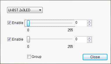
The uEye Cockpit also offers a dialog box for controlling the LEDs. To open the dialog box press the keys CTRL+SHIFT+L while the camera is initialized.

Fig. 470: uEye Cockpit - controlling LEDs