Opto Engineering TCBENCH
Telecentric optical benches for precision measurements

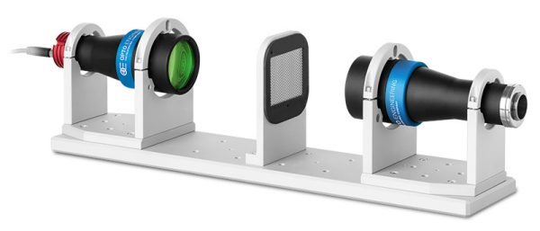
Opto Engineering TCBENCH optical bench for telecentric lenses Opto Engineering TCBENCH telecentric optical benches are pre-assembled, pre-aligned, and preset to ensure the highest accuracy for measurement applications. Simply attach your camera to the ready-to-use optical bench to begin measuring. The optical bench system is tested for optical performance as a whole system and includes a detailed test report with measured optical parameters. Each TCBENCH optical bench is a complete integrated optical system that includes:

  • 1 bi-telecentric lens for 2/3" detectors
  • 1 LTCLHP telecentric illuminator (green)
  • 2 CMHO mechanical clamps
  • 1 CMPT base-plate
  • 1 PTTC chrome-on-glass calibration pattern
  • 1 CMPH pattern holder

Features:

  • Pre-assembled, pre-aligned, and preset, and ready-to-use
  • High accuracty, high-end performance and cost-effective
  • Tested system with detailed test report

Opto Engineering telecentric lenses include a wide variety of lenses for area and line scan cameras. Contact us if you would like help choosing the right lens and lighting for your industrial machine vision applications.


Product User Guide Back focal adjustment LTCLHP manual
Get
Quote
  Main optical specifications Object field of view Advanced optical specifications Electrical specifications Mechanical specifications Data
Sheet
Part
number
Mag.Image
circle
diameter
Max
sensor
size
1/3"1/2"2/3"Working
distance
Working
ƒ/N
Telecentricity
typical
(max)
Distortion
typical
(max)
Depth
of
field
Light color, peak
wavelength
Supply
voltage
MountLengthWidthHeight
4.80 x 3.606.40 x 4.808.50 x 7.09
(x)(mm)(mm x mm)(mm x mm)(mm x mm)(mm)(deg)(%) (mm)(V)(mm)(mm)(mm)
1234510
TCBENCH0091.000112/3"4.80 x 3.606.40 x 4.808.50 x 7.0962.211< 0.08 (0.10)< 0.04 (0.08)0.6green, 520 nm12-24C2855679Download datasheet
TCBENCH0160.528112/3"9.09 x 6.8212.12 x 9.0916.10 x 13.4343.18< 0.06 (0.10)< 0.04 (0.07)1.5green, 520 nm12-24C3116681Download datasheet
TCBENCH0240.35112/3"13.71 x 10.2918.29 x 13.7124.29 x 20.2667.28< 0.08 (0.10)< 0.04 (0.10)3.4green, 520 nm12-24C3896681Download datasheet
TCBENCH0360.243112/3"19.75 x 14.8126.34 x 19.7534.98 x 29.18102.58< 0.04 (0.08)< 0.04 (0.10)7green, 520 nm12-24C545103141Download datasheet
TCBENCH0480.184112/3"26.09 x 19.5734.78 x 26.0946.20 x 38.53132.98< 0.08 (0.10)< 0.05 (0.10)12.2green, 520 nm12-24C653117148Download datasheet
TCBENCH0560.157112/3"30.57 x 22.9340.76 x 30.5754.14 x 45.16157.88< 0.05 (0.08)< 0.03 (0.08)16.8green, 520 nm12-24C712122150Download datasheet
TCBENCH0640.138112/3"34.78 x 26.0946.38 x 34.7861.59 x 51.38181.88< 0.05 (0.08)< 0.03 (0.07)21.7green, 520 nm12-24C845143161Download datasheet
TCBENCH0800.11112/3"43.64 x 32.7358.18 x 43.6477.27 x 64.45226.78< 0.04 (0.08)< 0.02 (0.10)34.2green, 520 nm12-24C936158168Download datasheet
TCBENCH0960.093112/3"51.61 x 38.7168.82 x 51.6191.40 x 76.24278.68< 0.06 (0.08)< 0.04 (0.08)47.9green, 520 nm12-24C1084185207Download datasheet

Notes

  1. Working distance: distance between the front end of the mechanics and the object. Set this distance within ± 3% of the nominal value for maximum resolution and minimum distortion.
  2. Working f-number (wf/N): the real f-number of a lens in operating conditions.
  3. Maximum angle between chief rays and optical axis on the object side. Typical (average production) values and maximum (guaranteed) values are listed.
  4. Percent deviation of the real image compared to an ideal, undistorted image. Typical (average production) values and maximum (guaranteed) values are listed. vAt the borders of the field depth the image can be still used for measurement but, to get a very sharp image, only half of the nominal field depth should be considered. Pixel size used for calculation is 3.45 μm.
  5. Object side, calculated with the Rayleigh criterion with λ= 520 nm
  6. At max forward current. Tolerance is ± 0.06V on forward voltage measurements.
  7. Used in continuous (not pulsed) mode.
  8. At pulse width ≤ 10 ms, duty cycle ≤ 10% condition. Built-in electronics board must be bypassed (see tech info).
  9. Measured from the camera flange of the objective lens to the electronic end of the illuminator. Cable, connector and mount thread excluded.