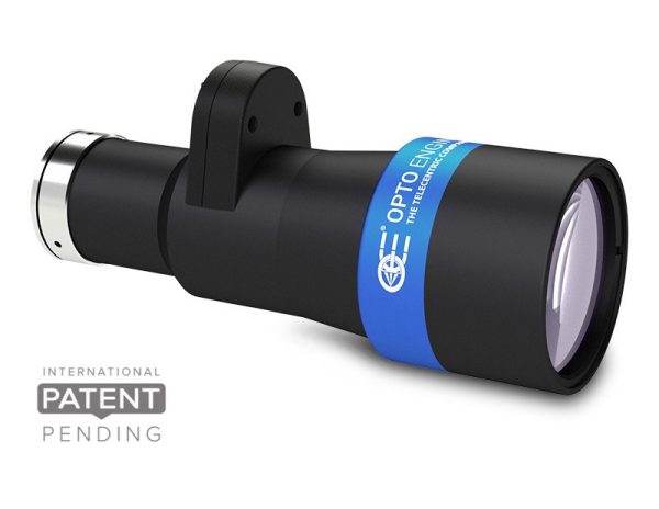
Opto Engineering TCEL Telecentric Lenses
telecentric optics and liquid lenses technology

Opto Engineering TCEL telecentric lens, telecentric optics and liquid lenses technology Opto Engineering Engineering TCEL telecentric lenses combine a perfect blend of telecentric optics and liquid lens technology. This technology enables a greatly increased depth of field (DOF) while maintaining the proportion of DOF and magnification — a feature that’s especially valuable for small fields of view.

TCEL lenses are ideal for inspection and measurement applications in industries such as electronics, semiconductors, and automotive. Their optical design provides excellent telecentricity with minimal distortion across their entire operating range.

The built-in, electronically controlled Optotune liquid lenses allow for quick and precise adjustments to optical power and focus, with response times in milliseconds. A compact USB-powered current source driver with free software can be used as a standalone solution or integrated into OEM designs. Communication uses an open serial protocol, compatible with any programming language on Windows or Linux (with C#, Labview, and Python source code available).

  • Perfect combination of telecentric optics and liquid lens technology
  • Integrated liquid lens extends DOF for the telecentric optics
  • Superior optical performance with minimal distortion
  • Electronically driven liquid lenses allow for fast and precise changes of focus
  • Detailed test report with measured optical parameters

Opto Engineering telecentric lenses include a wide variety of lenses for area and line scan cameras. Contact us if you would like help choosing the right lens for your industrial machine vision applications.


Product User Guide Back focal adjustment
Get
Quote
Part
number
Additional
notes
Main optical specifications Object field of view Advanced optical specifications Mechanical specifications Data
Sheet
Mag. Image
circle
diameter
Max
sensor
size
1/3" 1/1.8" 2/3" Working
distance
range
Working
ƒ/N
Telecentricity
typical
(max)
Distortion
typical
(max)
Depth
of
field
Mount Length Front
diameter
4.80 x 3.60 7.13 x 5.33 8.50 x 7.09
(x) (mm) (mm × mm) (mm × mm) (mm × mm) (mm) (deg) (%) (mm) (mm) (mm)
1 1 1 3 4 5 7 8 12
TCEL23036a0.243112/3"19.75 x 14.8129.34 x 21.9334.98 x 29.18122.9 - 73.28< 0.08 (0.1)< 0.04 (0.1)7C166.461Download datasheet
TCEL0500.5112/3"9.60 x 7.2014.26 x 10.6617.00 x 14.18146.3 - 112.212< 0.04 (0.08)< 0.1 (0.2)2.5C130.837.7Download datasheet
TCEL0660.67112/3"7.16 x 5.3710.64 x 7.9612.69 x 10.58146.1 - 112.312< 0.04 (0.08)< 0.1 (0.2)1.4C149.337.7Download datasheet
TCEL0750.75112/3"6.40 x 4.809.51 x 7.1111.33 x 9.45146.1 - 112.512< 0.07 (0.1)< 0.1 (0.2)1.1C15537.7Download datasheet
TCEL1001112/3"4.80 x 3.607.13 x 5.338.50 x 7.09142.0 - 118.012< 0.08 (0.1)< 0.05 (0.1)0.6C12637.7Download datasheet
TCEL150b1.5112/3"3.20 x 2.404.75 x 3.555.67 x 4.73142.0 - 118.016< 0.08 (0.1)< 0.05 (0.1)0.4C140.437.7Download datasheet
TCEL250b2.5112/3"1.92 x 1.442.85 x 2.133.40 x 2.84142.1 - 117.920< 0.08 (0.1)< 0.05 (0.1)0.2C15737.7Download datasheet
TCEL350b3.5112/3"1.37 x 1.032.04 x 1.522.43 x 2.03142.1 - 117.924< 0.08 (0.1)< 0.05 (0.1)0.1C174.737.7Download datasheet

Notes

  1. Field of views are calculated at 0 dpt power of the liquid lens.
  2. Working distance (nominal): distance between the front end of the mechanics and the object at 0 pdt power of the liquid lens.
  3. Minimum and maximum working distance are reported at nominal range of the liquid lens; maximum excursion may be larger.
  4. Working f-number (wf/N): the real f-number of a lens in operating conditions.
  5. Maximum angle between chief rays and optical axis on the object side, evaluated at 0 dpt power of the liquid lens. Typical (average production) values and maximum (guaranteed) values are listed.
  6. Maximum values calculated in the range -2 to +3 dpt of the liquid lens.
  7. Percent deviation of the real image compared to an ideal, undistorted image, , evaluated at 0 dpt power of the liquid lens. Typical (average production) values and maximum (guaranteed) values are listed.
  8. At the limits of the depth of field, the image can still be used for measurements. For a very sharp image, however, only half of the depth of field should be considered. Pixel size used for calculation is 3.45 μm.
  9. Object side, calculated with the Rayleigh criterion with λ= 520 nm
  10. Typical at 30°C, 0 to ±250 mA step.
  11. Indicates the availability of an integrated camera phase adjustment feature.
  12. Measured from the front end of the mechanics to the camera flange.

Additional Notes

  1. Performances calculated with monochromatic light (LED emission); performance range in white light is smaller.
  2. Performances guaranteed when used with vertical optical axis; when used with horizontal optical axis performances drop due to gravity induced aberrations of the liquid lens.